How to Use Wi-Fi HaLow Module for Seeed Studio XIAO: Examples, Pinouts, and Specs
Introduction
The Wi-Fi HaLow Module for Seeed Studio XIAO is a low-power wireless communication module designed for long-range IoT applications. It leverages the IEEE 802.11ah standard, enabling efficient data transmission over extended distances while consuming minimal power. This module is fully compatible with the Seeed Studio XIAO microcontroller series, making it an excellent choice for IoT projects requiring reliable and energy-efficient connectivity.
Explore Projects Built with Wi-Fi HaLow Module for Seeed Studio XIAO


Explore Projects Built with Wi-Fi HaLow Module for Seeed Studio XIAO
Common Applications and Use Cases
- Smart agriculture and environmental monitoring
- Industrial IoT (IIoT) and smart factories
- Home automation and smart appliances
- Long-range sensor networks
- Wearable devices with low-power connectivity
Technical Specifications
Key Technical Details
| Parameter | Specification |
|---|---|
| Wireless Standard | IEEE 802.11ah (Wi-Fi HaLow) |
| Frequency Band | Sub-1 GHz (typically 900 MHz) |
| Data Rate | Up to 347 Mbps |
| Range | Up to 1 km (line of sight) |
| Power Consumption | Ultra-low power for IoT applications |
| Operating Voltage | 3.3V |
| Interface | UART, SPI, or I2C |
| Dimensions | Compact form factor for XIAO boards |
| Compatibility | Seeed Studio XIAO microcontroller |
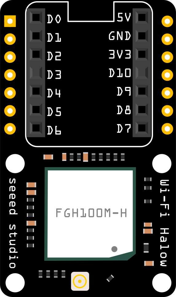
Pin Configuration and Descriptions
The Wi-Fi HaLow Module is designed to interface seamlessly with the Seeed Studio XIAO microcontroller. Below is the pin configuration:
| Pin Number | Pin Name | Description |
|---|---|---|
| 1 | VCC | Power supply input (3.3V) |
| 2 | GND | Ground |
| 3 | TX | UART Transmit |
| 4 | RX | UART Receive |
| 5 | SPI_MOSI | SPI Master Out Slave In |
| 6 | SPI_MISO | SPI Master In Slave Out |
| 7 | SPI_SCK | SPI Clock |
| 8 | SPI_CS | SPI Chip Select |
| 9 | I2C_SDA | I2C Data Line |
| 10 | I2C_SCL | I2C Clock Line |
| 11 | RESET | Module reset pin |
| 12 | WAKE | Wake-up pin for low-power mode |
Usage Instructions
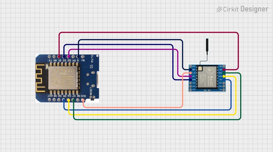
How to Use the Component in a Circuit
- Power Supply: Connect the VCC pin to a 3.3V power source and the GND pin to ground.
- Communication Interface: Choose the desired communication protocol (UART, SPI, or I2C) and connect the corresponding pins to the Seeed Studio XIAO microcontroller.
- For UART: Connect TX and RX pins to the XIAO's RX and TX pins, respectively.
- For SPI: Connect SPI_MOSI, SPI_MISO, SPI_SCK, and SPI_CS to the corresponding SPI pins on the XIAO.
- For I2C: Connect I2C_SDA and I2C_SCL to the XIAO's I2C pins.
- Reset and Wake: Optionally, connect the RESET and WAKE pins to GPIO pins on the XIAO for additional control.
- Antenna: Attach an appropriate antenna to the module for optimal range and performance.
Important Considerations and Best Practices
- Ensure the power supply is stable and within the specified 3.3V range to avoid damaging the module.
- Use proper pull-up resistors for I2C communication if not already integrated into the module.
- Place the module away from high-frequency noise sources to maintain signal integrity.
- For long-range communication, ensure a clear line of sight between the module and the receiving device.
Example Code for Arduino UNO-Compatible XIAO
Below is an example of how to initialize the Wi-Fi HaLow Module using UART communication with the Seeed Studio XIAO:
#include <SoftwareSerial.h>

// Define the UART pins for the Wi-Fi HaLow Module
#define RX_PIN 2  // XIAO's RX pin connected to module's TX
#define TX_PIN 3  // XIAO's TX pin connected to module's RX

// Create a SoftwareSerial object for communication
SoftwareSerial wifiHalow(RX_PIN, TX_PIN);

void setup() {
  // Initialize serial communication with the module
  Serial.begin(9600); // For debugging via USB
  wifiHalow.begin(9600); // Communication with Wi-Fi HaLow Module

  Serial.println("Initializing Wi-Fi HaLow Module...");
  wifiHalow.println("AT"); // Send an AT command to test communication

  delay(1000); // Wait for the module to respond

  if (wifiHalow.available()) {
    // Read and print the module's response
    while (wifiHalow.available()) {
      char c = wifiHalow.read();
      Serial.print(c);
    }
    Serial.println("\nWi-Fi HaLow Module initialized successfully!");
  } else {
    Serial.println("Failed to communicate with Wi-Fi HaLow Module.");
  }
}

void loop() {
  // Example: Send data to the module
  wifiHalow.println("Hello, Wi-Fi HaLow!");
  delay(2000); // Wait for 2 seconds before sending again
}
Notes:
- Replace
9600with the appropriate baud rate for your module if different. - Ensure the RX and TX pins are correctly connected to avoid communication errors.
Troubleshooting and FAQs
Common Issues and Solutions
No Response from the Module
- Cause: Incorrect wiring or baud rate mismatch.
- Solution: Double-check the connections and ensure the baud rate in the code matches the module's default baud rate.
Unstable Communication
- Cause: Power supply issues or interference.
- Solution: Use a stable 3.3V power source and keep the module away from high-frequency noise sources.
Limited Range
- Cause: Poor antenna placement or obstructions.
- Solution: Ensure the antenna is properly connected and positioned for optimal signal strength. Minimize physical obstructions between the module and the receiving device.
Module Not Entering Low-Power Mode
- Cause: WAKE pin not configured correctly.
- Solution: Verify the WAKE pin is connected to a GPIO pin and properly controlled in the code.
FAQs
Q: Can this module be used with other microcontrollers?
A: Yes, the module can be used with any microcontroller that supports UART, SPI, or I2C communication.Q: What is the maximum range of the module?
A: The module can achieve a range of up to 1 km in line-of-sight conditions.Q: Does the module support encryption for secure communication?
A: Yes, the module supports standard Wi-Fi security protocols, including WPA3.Q: Can I use this module for battery-powered applications?
A: Absolutely! The module is designed for ultra-low power consumption, making it ideal for battery-powered IoT devices.