How to Use RCBO: Examples, Pinouts, and Specs
Introduction
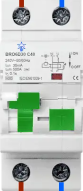
A Residual Current Circuit Breaker with Overcurrent protection (RCBO) is a critical safety device in electrical systems. It combines the functionality of a Residual Current Device (RCD) and a Miniature Circuit Breaker (MCB). The RCBO is designed to protect against two major electrical hazards:
- Earth faults (leakage currents): Prevents electric shocks by detecting and disconnecting circuits with leakage currents.
- Overcurrent (overload and short circuits): Protects wiring and connected devices from damage caused by excessive current.
RCBOs are widely used in residential, commercial, and industrial electrical installations to ensure safety and compliance with electrical standards.
Explore Projects Built with RCBO
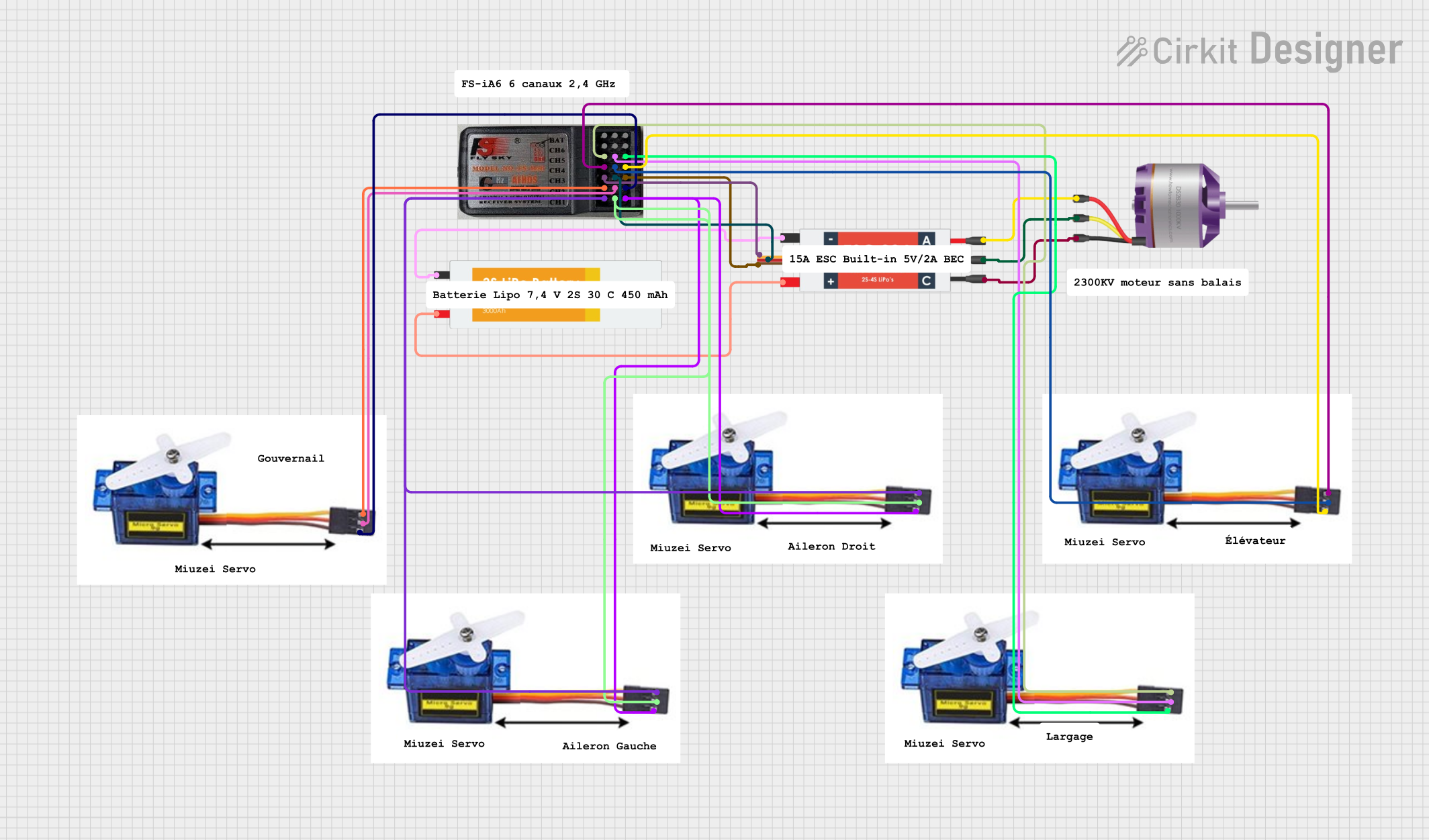
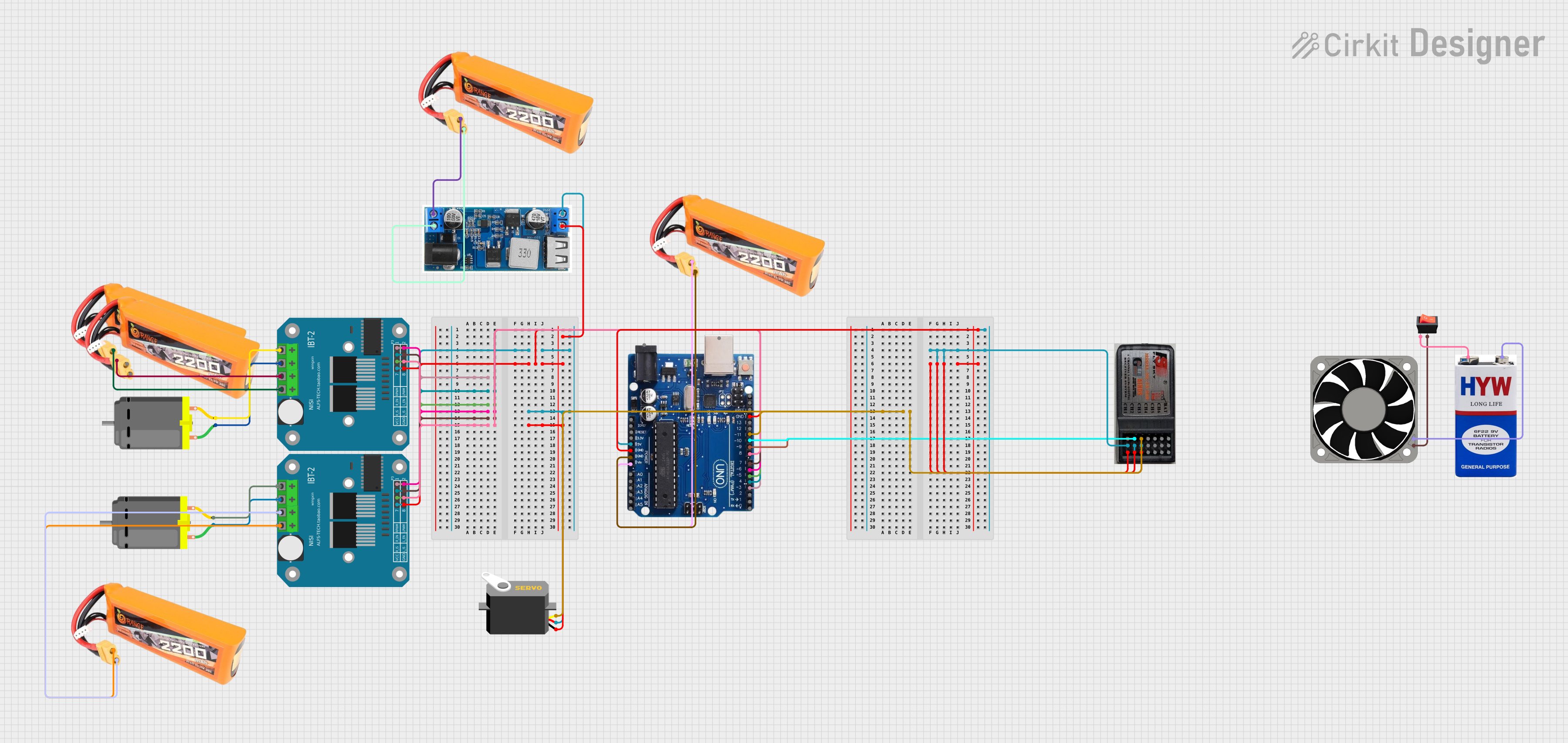
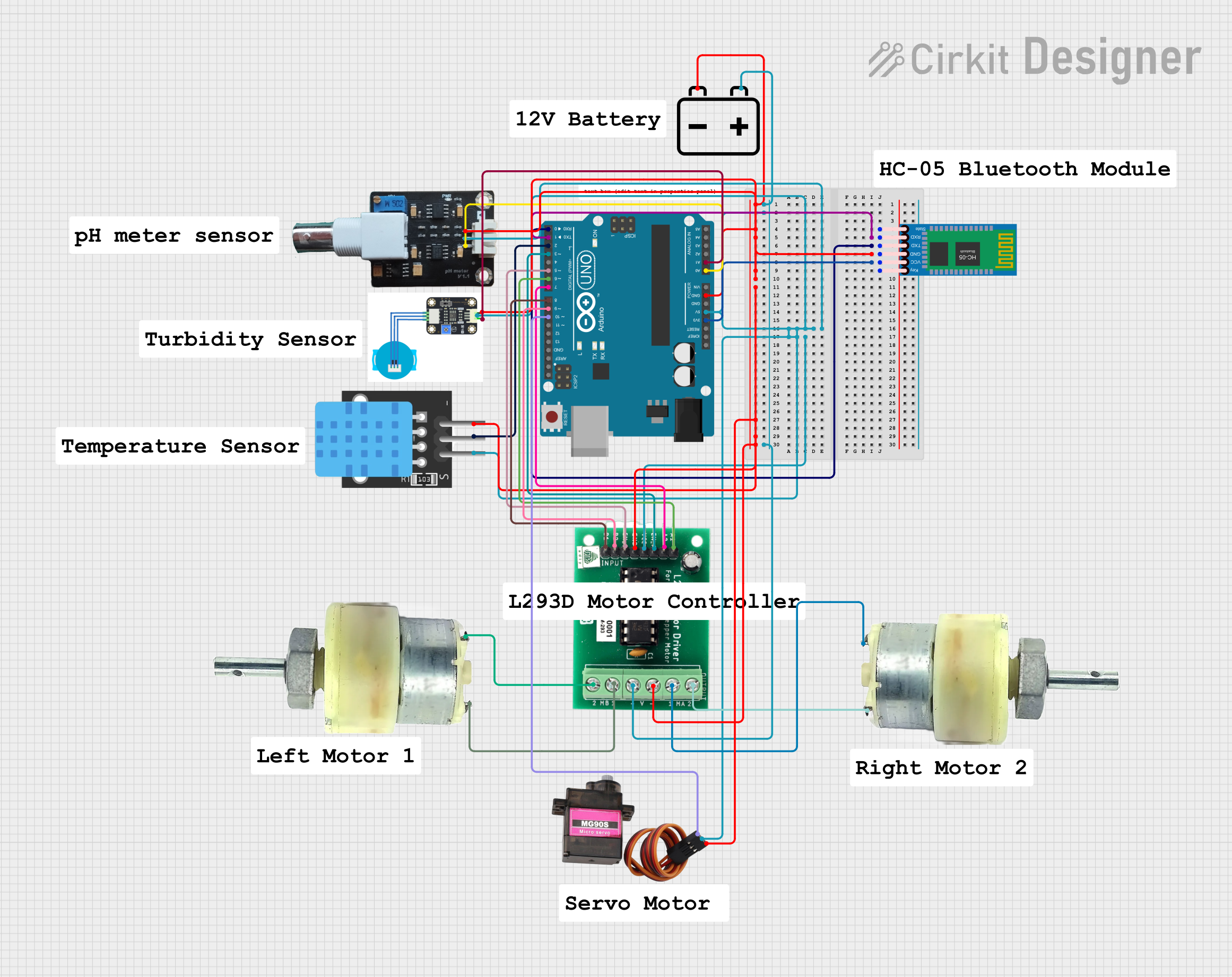
Explore Projects Built with RCBO
Common Applications
- Residential electrical distribution boards for individual circuit protection.
- Commercial buildings to safeguard critical equipment and lighting circuits.
- Industrial environments to protect machinery and prevent fire hazards.
- Outdoor installations where additional protection against electric shock is required.
Technical Specifications
Key Technical Details
| Parameter | Value |
|---|---|
| Rated Voltage (Un) | 230/240V AC (single-phase) or 400V AC (three-phase) |
| Rated Current (In) | Typically 6A, 10A, 16A, 20A, 32A, 40A |
| Rated Residual Current (IΔn) | 10mA, 30mA, or 100mA (depending on application) |
| Breaking Capacity | 6kA or 10kA (depending on model and standard compliance) |
| Tripping Curve | B, C, or D curve (defines response to overcurrent) |
| Frequency | 50Hz or 60Hz |
| Operating Temperature Range | -5°C to +40°C |
| Standards Compliance | IEC/EN 61009-1 |
Pin Configuration and Descriptions
RCBOs typically have terminals for connecting the live and neutral wires. Below is a general description of the terminal configuration:
| Terminal | Description |
|---|---|
| L (Line In) | Input terminal for the live wire from the power source. |
| N (Neutral In) | Input terminal for the neutral wire from the power source. |
| L (Line Out) | Output terminal for the live wire to the load (protected circuit). |
| N (Neutral Out) | Output terminal for the neutral wire to the load (protected circuit). |
| Test Button | A button to simulate a fault condition and verify the RCBO's functionality. |
Usage Instructions
How to Use the RCBO in a Circuit
Installation:
- Ensure the power supply is turned off before installation.
- Mount the RCBO on a DIN rail in the distribution board.
- Connect the input terminals (L and N) to the power source.
- Connect the output terminals (L and N) to the load circuit.
- Tighten all terminal screws securely to avoid loose connections.
Testing:
- After installation, press the test button to verify the RCBO's functionality.
- The RCBO should trip immediately, indicating proper operation.
Operation:
- Once installed and tested, the RCBO will continuously monitor the circuit for earth faults and overcurrent conditions.
- In the event of a fault, the RCBO will trip, disconnecting the circuit to prevent hazards.
Important Considerations and Best Practices
- Select an RCBO with the appropriate rated current (In) and residual current (IΔn) for your application.
- Use a 30mA RCBO for personal protection against electric shock in residential installations.
- Ensure proper wiring and polarity during installation to avoid malfunction.
- Regularly test the RCBO using the test button to ensure it remains functional.
- Avoid using RCBOs in circuits with high leakage currents (e.g., motors) unless specifically designed for such applications.
Troubleshooting and FAQs
Common Issues and Solutions
| Issue | Possible Cause | Solution |
|---|---|---|
| RCBO trips immediately after installation. | Incorrect wiring or reversed polarity. | Verify and correct the wiring connections. |
| RCBO does not trip when the test button is pressed. | Faulty RCBO or insufficient test current. | Replace the RCBO or check the test button circuit. |
| Frequent tripping without apparent cause. | Leakage current in the circuit exceeds the RCBO's rating. | Inspect the circuit for faulty appliances or insulation issues. |
| RCBO trips during high inrush current events. | Inappropriate tripping curve (e.g., B curve for motor loads). | Use an RCBO with a C or D tripping curve for circuits with high inrush current. |
| RCBO does not reset after tripping. | Persistent fault in the circuit. | Identify and resolve the fault before attempting to reset the RCBO. |
FAQs
Can I use an RCBO in place of an RCD or MCB?
Yes, an RCBO combines the functions of both an RCD and an MCB, providing protection against earth faults and overcurrent in a single device.How often should I test my RCBO?
It is recommended to test the RCBO using the test button at least once every six months to ensure proper functionality.What is the difference between a 30mA and a 100mA RCBO?
A 30mA RCBO is designed for personal protection against electric shock, while a 100mA RCBO is typically used for fire protection in circuits with higher leakage currents.Can an RCBO protect against lightning strikes?
No, an RCBO is not designed to protect against lightning strikes. Use a surge protection device (SPD) for this purpose.What happens if the RCBO trips frequently?
Frequent tripping indicates a persistent fault or an overloaded circuit. Inspect the circuit and connected devices to identify and resolve the issue.