How to Use Arduino Mega 2560: Examples, Pinouts, and Specs
Introduction
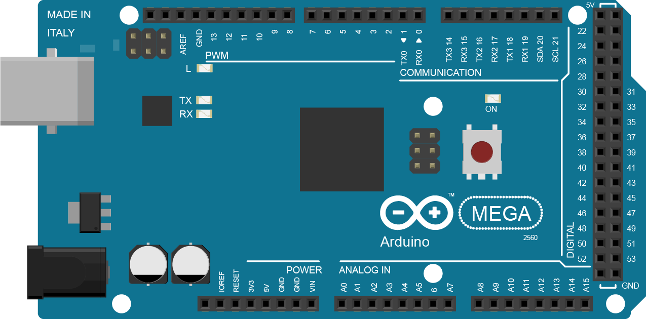
The Arduino Mega 2560 is a microcontroller board based on the ATmega2560 processor. It is an integral part of the Arduino platform, known for its extended I/O capabilities and suitability for complex projects. The Mega 2560 is commonly used in robotics, large-scale automation projects, and situations where multiple sensors and actuators are required.
Explore Projects Built with Arduino Mega 2560
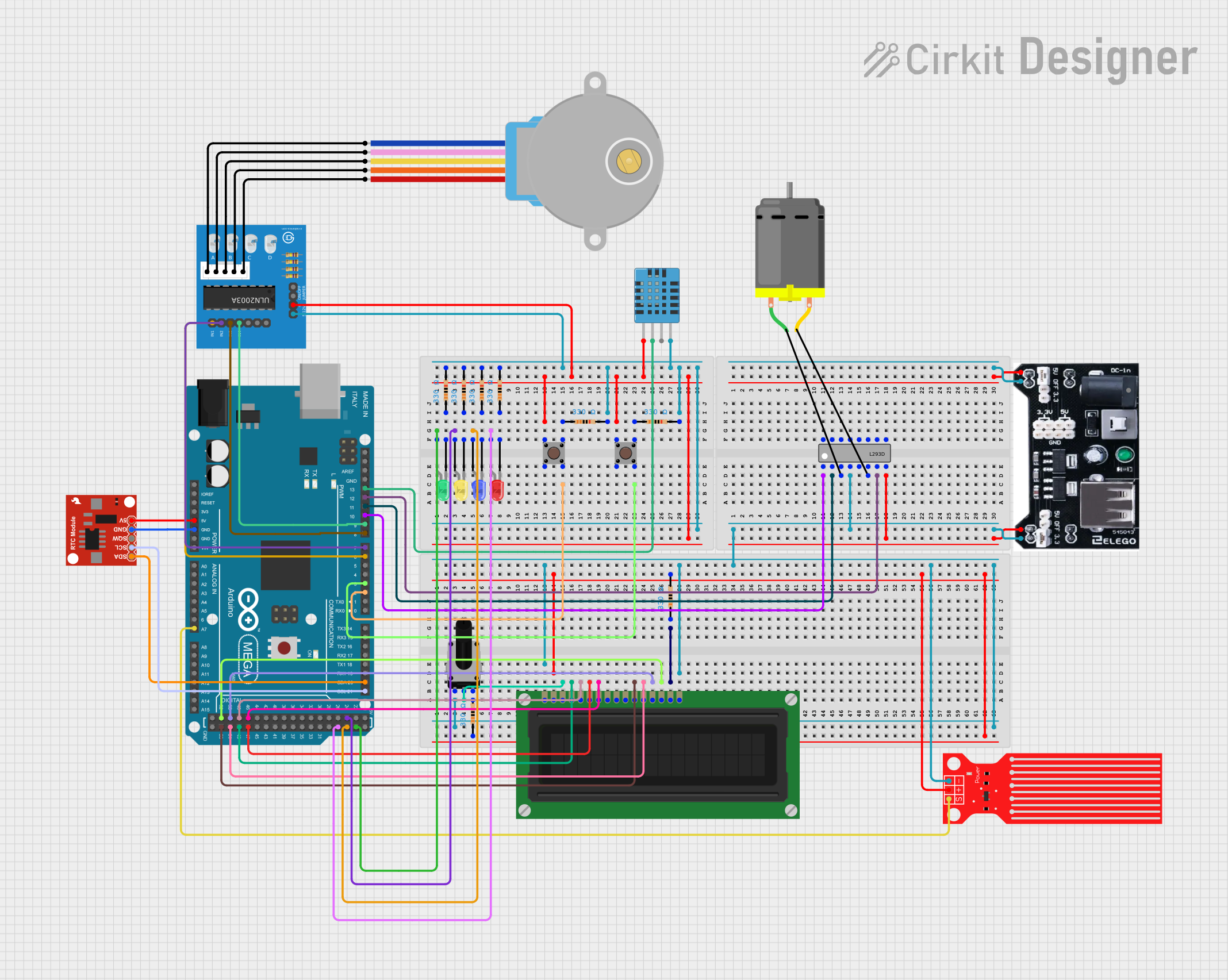
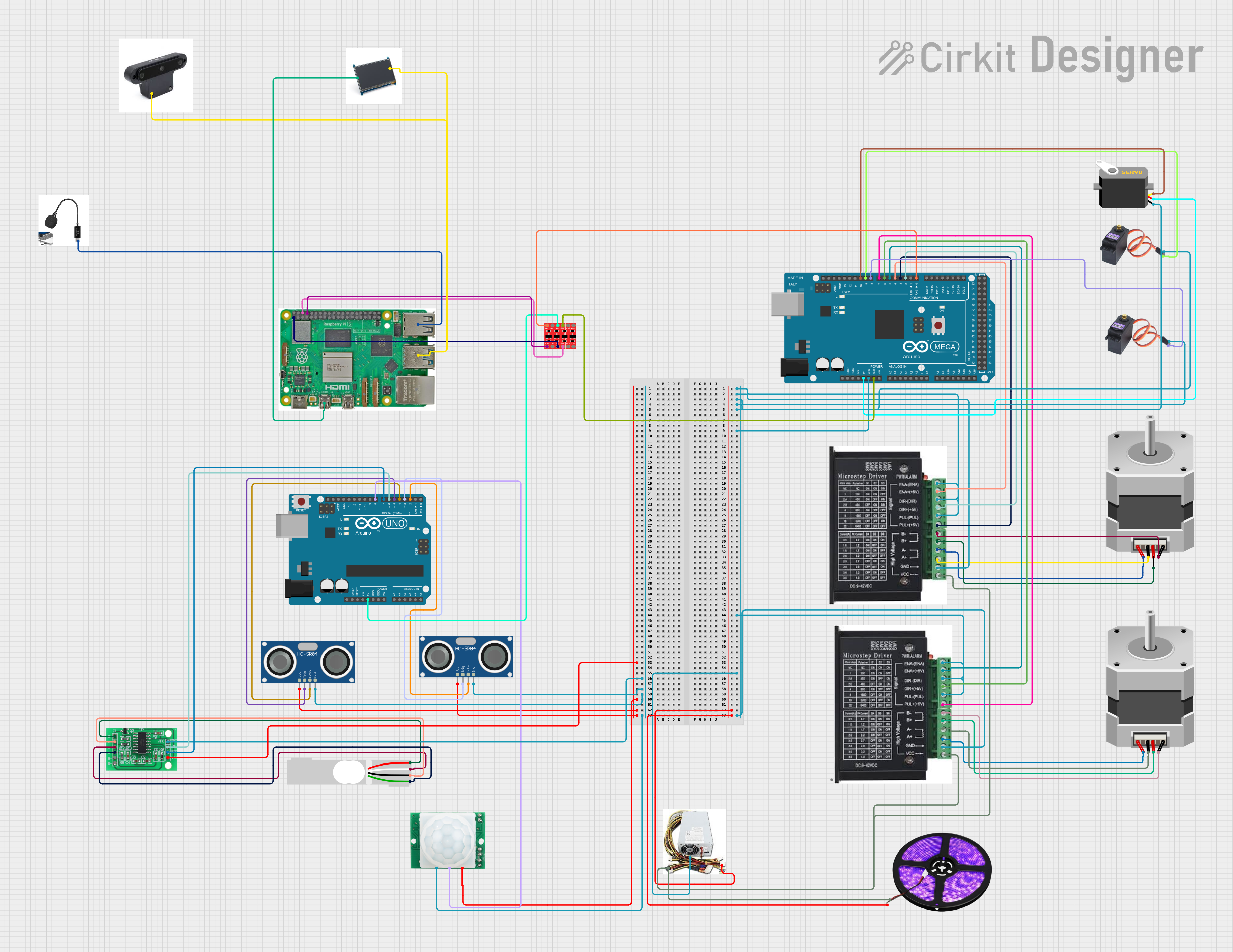
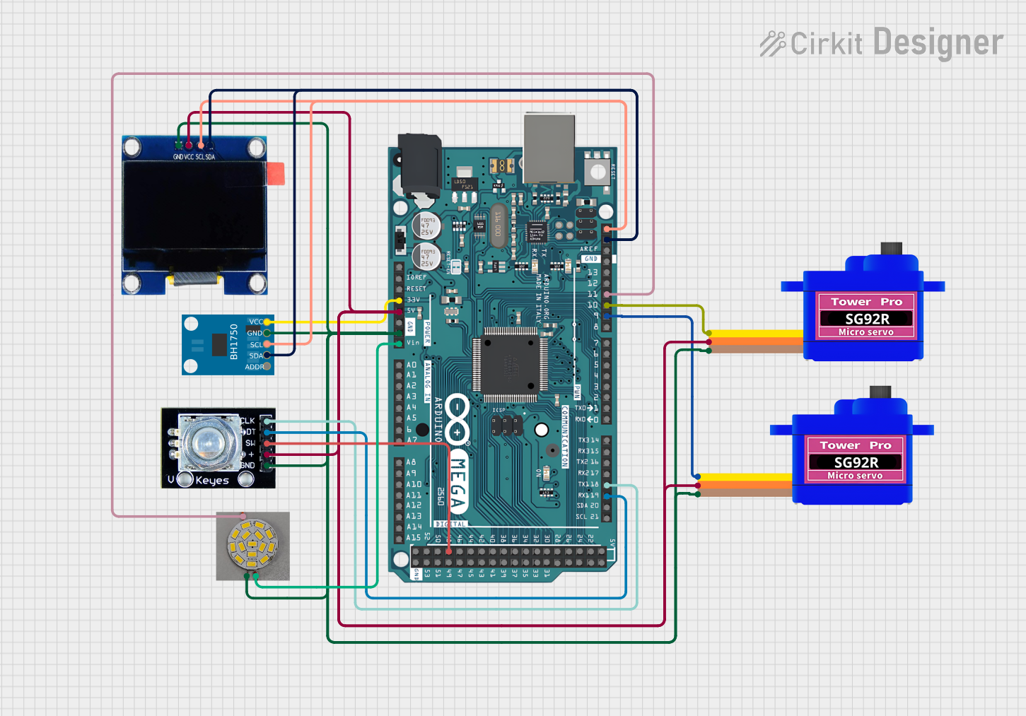
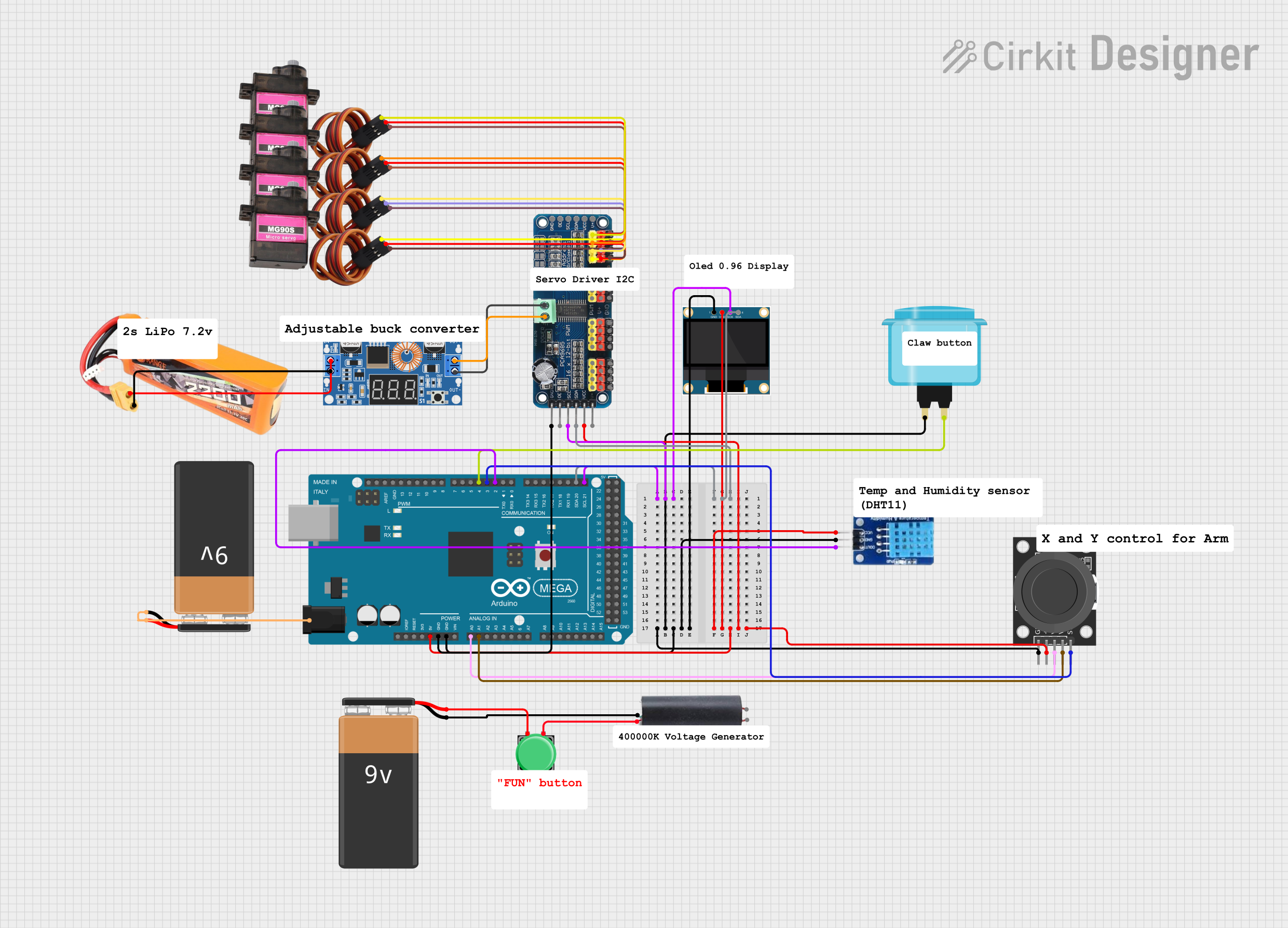
Explore Projects Built with Arduino Mega 2560
Common Applications and Use Cases
- Robotics
- 3D printers
- Home automation systems
- Complex art installations
- Multichannel audio systems
- Educational and prototyping projects
Technical Specifications
Key Technical Details
- Microcontroller: ATmega2560
- Operating Voltage: 5V
- Input Voltage (recommended): 7-12V
- Input Voltage (limits): 6-20V
- Digital I/O Pins: 54 (of which 15 provide PWM output)
- Analog Input Pins: 16
- DC Current per I/O Pin: 20 mA
- DC Current for 3.3V Pin: 50 mA
- Flash Memory: 256 KB of which 8 KB used by bootloader
- SRAM: 8 KB
- EEPROM: 4 KB
- Clock Speed: 16 MHz
- LED_BUILTIN: Pin 13
Pin Configuration and Descriptions
| Pin Number | Function | Description |
|---|---|---|
| 1-54 | Digital I/O | Digital input/output pins, PWM(*) on 2-13,44-46 |
| A0-A15 | Analog Input | Analog input pins |
| TX0-TX3 | UART Transmit | Serial transmission pins |
| RX0-RX3 | UART Receive | Serial receive pins |
| SDA | I2C Data | I2C data line |
| SCL | I2C Clock | I2C clock line |
| 5V | Power Output | Regulated 5V output |
| 3.3V | Power Output | Regulated 3.3V output |
| GND | Ground | Ground pins |
| VIN | Voltage Input | Input voltage to the Arduino board |
| RESET | Reset | Resets the microcontroller |
(*) PWM: Pulse Width Modulation
Usage Instructions
How to Use the Arduino Mega 2560 in a Circuit
Powering the Board:
- Connect a 7-12V power supply to the power jack or VIN pin.
- Alternatively, connect the board to a computer via USB cable for power and programming.
Connecting I/O Devices:
- Digital devices can be connected to digital I/O pins.
- Analog sensors should be connected to the analog input pins.
- Use PWM pins for devices that require variable power, like motors.
Programming the Board:
- Use the Arduino IDE to write and upload sketches to the board.
- Select "Arduino Mega or Mega 2560" as the board type in the IDE.
Serial Communication:
- Utilize the UART pins for serial communication.
- The Mega 2560 has four hardware serial ports (Serial, Serial1, Serial2, Serial3).
Important Considerations and Best Practices
- Ensure that the total current draw from all pins does not exceed the specified limits.
- Use external power sources when connecting devices that draw more current than the board can provide.
- Avoid exposing the board to extreme temperatures or moisture.
- Always disconnect the board from power sources before making or altering connections.
Troubleshooting and FAQs
Common Issues
Board not recognized by computer:
- Check the USB cable and connections.
- Ensure the correct drivers are installed.
- Try resetting the board or using another USB port.
Sketch not uploading:
- Verify the correct board and port are selected in the Arduino IDE.
- Check for errors in the code and ensure the correct bootloader is used.
Unexpected behavior in circuits:
- Double-check wiring and connections.
- Ensure power supply is adequate and stable.
- Review the code for logical errors or incorrect pin assignments.
FAQs
Q: Can I use the Arduino Mega 2560 with a battery? A: Yes, you can power the board with a battery within the input voltage limits.
Q: How many devices can I connect to the Mega 2560? A: You can connect devices to all available pins, but ensure the total current does not exceed board limits.
Q: Is the Arduino Mega 2560 compatible with all Arduino shields? A: Most shields designed for the Arduino Uno are compatible, but check shield specifications for voltage and pin compatibility.
Q: Can I use the Arduino Mega 2560 for commercial products? A: Yes, the Mega 2560 can be used in commercial products, but consider the open-source license and attribution requirements.
For further assistance, consult the Arduino community forums or the official Arduino help pages.
Example Code for Arduino UNO
Here's a simple example of blinking an LED connected to pin 13 on the Arduino Mega 2560:
// Define the LED pin
const int ledPin = 13;

// The setup function runs once when you press reset or power the board
void setup() {
  // Initialize digital pin LED_BUILTIN as an output.
  pinMode(ledPin, OUTPUT);
}

// The loop function runs over and over again forever
void loop() {
  digitalWrite(ledPin, HIGH);   // Turn the LED on (HIGH is the voltage level)
  delay(1000);                  // Wait for a second
  digitalWrite(ledPin, LOW);    // Turn the LED off by making the voltage LOW
  delay(1000);                  // Wait for a second
}
This code will blink the onboard LED on and off every second. It's a basic example to demonstrate how to control a digital output.