How to Use 5 channel ir array: Examples, Pinouts, and Specs
Robojunkies 5-Channel Infrared (IR) Array Documentation
1. Introduction
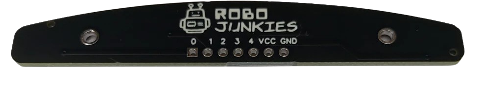
The Robojunkies 5-Channel Infrared (IR) Array is a versatile sensor module designed for applications requiring precise infrared signal detection or transmission. This component features five independent IR sensors arranged in a linear configuration, enabling it to detect objects, track lines, or sense proximity across multiple channels. Its compact design and ease of integration make it ideal for robotics, automation, and embedded systems.
Common Applications
- Line Following Robots: Detect and follow lines on a surface using reflective IR sensing.
- Obstacle Detection: Identify objects or barriers in the path of a robot or device.
- Edge Detection: Prevent devices from falling off edges or platforms.
- Position Sensing: Determine the position of objects in industrial or automation systems.
- Proximity Sensing: Detect nearby objects for interactive systems or safety mechanisms.
2. Technical Specifications
The following table outlines the key technical details of the Robojunkies 5-Channel IR Array:
| Parameter | Specification |
|---|---|
| Operating Voltage | 3.3V to 5V DC |
| Operating Current | ~20mA (typical) |
| Number of Channels | 5 |
| Sensor Type | Infrared (IR) Reflective Sensors |
| Detection Range | 2mm to 10mm (depending on surface) |
| Output Type | Digital (High/Low) |
| Dimensions | 70mm x 15mm x 10mm |
| Mounting Holes | 2 (M3 screws) |
| Manufacturer | Robojunkies |
Pin Configuration
The module has a 7-pin header for interfacing with microcontrollers or other devices. The pinout is as follows:
| Pin | Name | Description |
|---|---|---|
| 1 | VCC | Power supply input (3.3V to 5V DC). |
| 2 | GND | Ground connection. |
| 3 | OUT1 | Digital output for Channel 1 (High/Low based on IR detection). |
| 4 | OUT2 | Digital output for Channel 2 (High/Low based on IR detection). |
| 5 | OUT3 | Digital output for Channel 3 (High/Low based on IR detection). |
| 6 | OUT4 | Digital output for Channel 4 (High/Low based on IR detection). |
| 7 | OUT5 | Digital output for Channel 5 (High/Low based on IR detection). |
3. Usage Instructions
Connecting the IR Array to a Microcontroller
To use the Robojunkies 5-Channel IR Array with a microcontroller (e.g., Arduino UNO), follow these steps:
- Power the Module: Connect the
VCCpin to the 5V pin on the Arduino and theGNDpin to the Arduino's GND. - Connect Outputs: Connect the
OUT1toOUT5pins to the desired digital input pins on the Arduino (e.g., D2 to D6). - Write Code: Use the Arduino IDE to write a program that reads the digital signals from the IR array and performs actions based on the sensor readings.
Example Circuit Diagram
Below is a simple connection diagram for the IR array with an Arduino UNO:
IR Array Pin   ->   Arduino Pin
-------------------------------
VCC            ->   5V
GND            ->   GND
OUT1           ->   D2
OUT2           ->   D3
OUT3           ->   D4
OUT4           ->   D5
OUT5           ->   D6
Arduino Code Example
The following code demonstrates how to read the outputs of the IR array and print the results to the Serial Monitor:
// Define the pins connected to the IR array outputs
const int irPins[5] = {2, 3, 4, 5, 6};

void setup() {
  // Initialize serial communication for debugging
  Serial.begin(9600);

  // Set IR pins as inputs
  for (int i = 0; i < 5; i++) {
    pinMode(irPins[i], INPUT);
  }
}

void loop() {
  // Read and print the state of each IR sensor
  Serial.print("IR Sensor States: ");
  for (int i = 0; i < 5; i++) {
    int sensorState = digitalRead(irPins[i]);
    Serial.print(sensorState);
    Serial.print(" "); // Add space between sensor states
  }
  Serial.println(); // Move to the next line
  delay(100); // Small delay for readability
}
Important Considerations
- Surface Reflectivity: The detection range and accuracy depend on the reflectivity of the surface. Dark or matte surfaces may reduce sensitivity.
- Ambient Light: Strong ambient light or sunlight can interfere with IR detection. Use the module in controlled lighting conditions for best results.
- Power Supply: Ensure a stable power supply to avoid erratic behavior.
4. Troubleshooting and FAQs
Common Issues and Solutions
| Issue | Possible Cause | Solution |
|---|---|---|
| No output from the module | Incorrect wiring or loose connections | Verify all connections and ensure proper power supply. |
| Erratic or inconsistent readings | Ambient light interference | Use the module in a controlled lighting environment or shield it from light. |
| Reduced detection range | Surface is too dark or non-reflective | Test with a lighter or more reflective surface. |
| All outputs are always HIGH or LOW | Faulty module or incorrect pin mapping | Check the pin connections and test the module with a multimeter. |
Frequently Asked Questions
Can I use this module with a 3.3V microcontroller?
- Yes, the module supports an operating voltage range of 3.3V to 5V.
What is the maximum detection range?
- The module can detect objects up to 10mm away, depending on the surface reflectivity.
Can I use this module for analog output?
- No, the module provides digital outputs (High/Low) only.
How do I mount the module on a robot?
- The module has two mounting holes compatible with M3 screws for easy installation.
5. Additional Resources
This documentation provides a comprehensive guide to using the Robojunkies 5-Channel IR Array. Whether you're building a line-following robot or experimenting with object detection, this module is a reliable and easy-to-use solution. For further assistance, refer to the troubleshooting section or contact Robojunkies support.
Explore Projects Built with 5 channel ir array
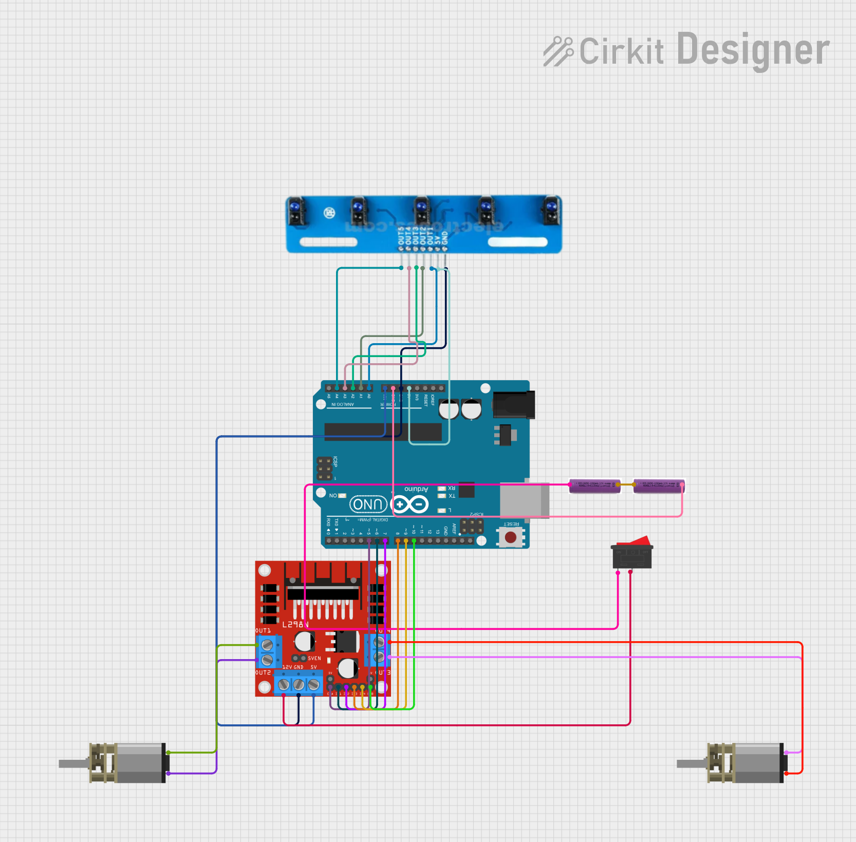
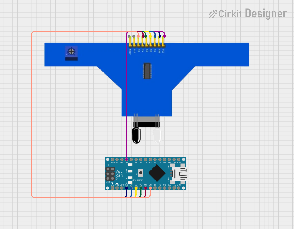
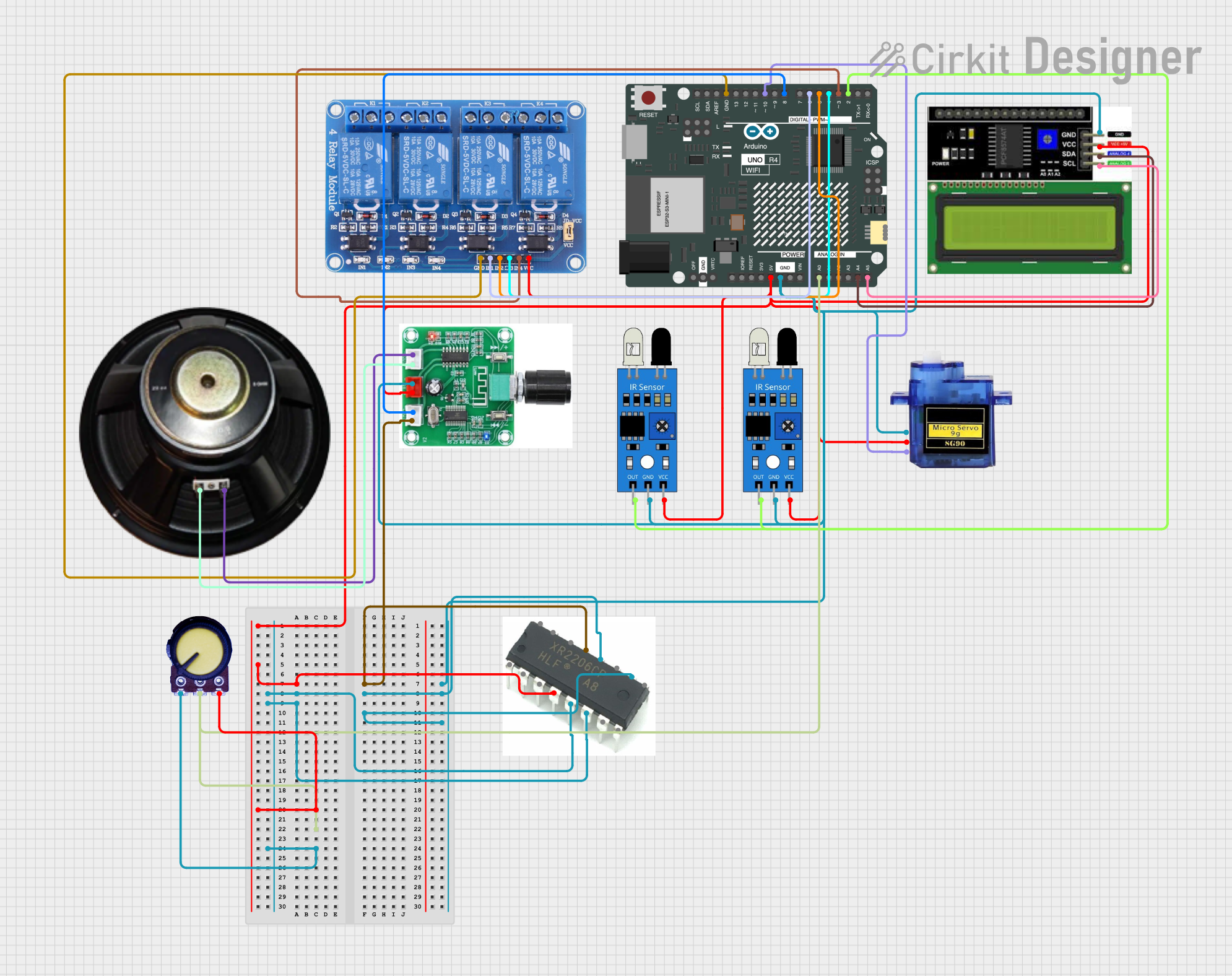
Explore Projects Built with 5 channel ir array