How to Use Greycode Board: Examples, Pinouts, and Specs
Introduction
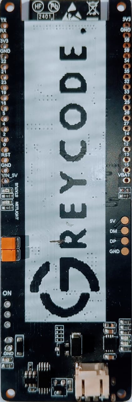
The Greycode Board, manufactured by Arduino (Part ID: UNO), is a specialized circuit component designed to demonstrate and implement Grey code. Grey code is a binary numeral system where two successive values differ in only one bit, making it highly useful in digital systems for error correction and state transition simplification. This board is ideal for educational purposes, prototyping, and applications requiring precise state transitions, such as rotary encoders, digital communication systems, and error detection mechanisms.
Explore Projects Built with Greycode Board


Explore Projects Built with Greycode Board
Common Applications and Use Cases
- Rotary encoders for position sensing
- Error correction in digital communication
- Simplifying state transitions in finite state machines
- Educational demonstrations of Grey code principles
- Robotics and automation systems
Technical Specifications
Key Technical Details
- Manufacturer: Arduino
- Part ID: UNO
- Operating Voltage: 5V DC
- Current Consumption: 20mA (typical)
- Output Format: 4-bit Grey code
- Input Type: Digital
- Operating Temperature: -40°C to 85°C
- Dimensions: 50mm x 30mm
Pin Configuration and Descriptions
The Greycode Board has a simple pinout for easy integration into digital systems. Below is the pin configuration:
| Pin | Name | Description |
|---|---|---|
| 1 | VCC | Power supply input (5V DC). |
| 2 | GND | Ground connection. |
| 3 | OUT0 | Grey code output bit 0 (LSB). |
| 4 | OUT1 | Grey code output bit 1. |
| 5 | OUT2 | Grey code output bit 2. |
| 6 | OUT3 | Grey code output bit 3 (MSB). |
| 7 | EN | Enable pin. Set HIGH to activate the board, LOW to disable. |
| 8 | CLK | Clock input for synchronizing Grey code transitions (optional, for advanced use). |
Usage Instructions
How to Use the Greycode Board in a Circuit
- Power the Board: Connect the
VCCpin to a 5V DC power source and theGNDpin to ground. - Enable the Board: Set the
ENpin HIGH to activate the board. If this pin is LOW, the board will remain inactive. - Connect Outputs: Use the
OUT0toOUT3pins to read the 4-bit Grey code output. These outputs can be connected to a microcontroller or digital logic circuit. - Optional Clock Input: If precise timing is required, connect a clock signal to the
CLKpin. This will synchronize the Grey code transitions with the clock signal.
Important Considerations and Best Practices
- Ensure the power supply is stable and within the specified 5V range to avoid damage to the board.
- Use pull-down resistors on the output pins if the connected microcontroller or circuit requires it.
- If using the
CLKpin, ensure the clock signal is clean and within the operating frequency range of the board. - Avoid leaving the
ENpin floating; always connect it to a defined HIGH or LOW state.
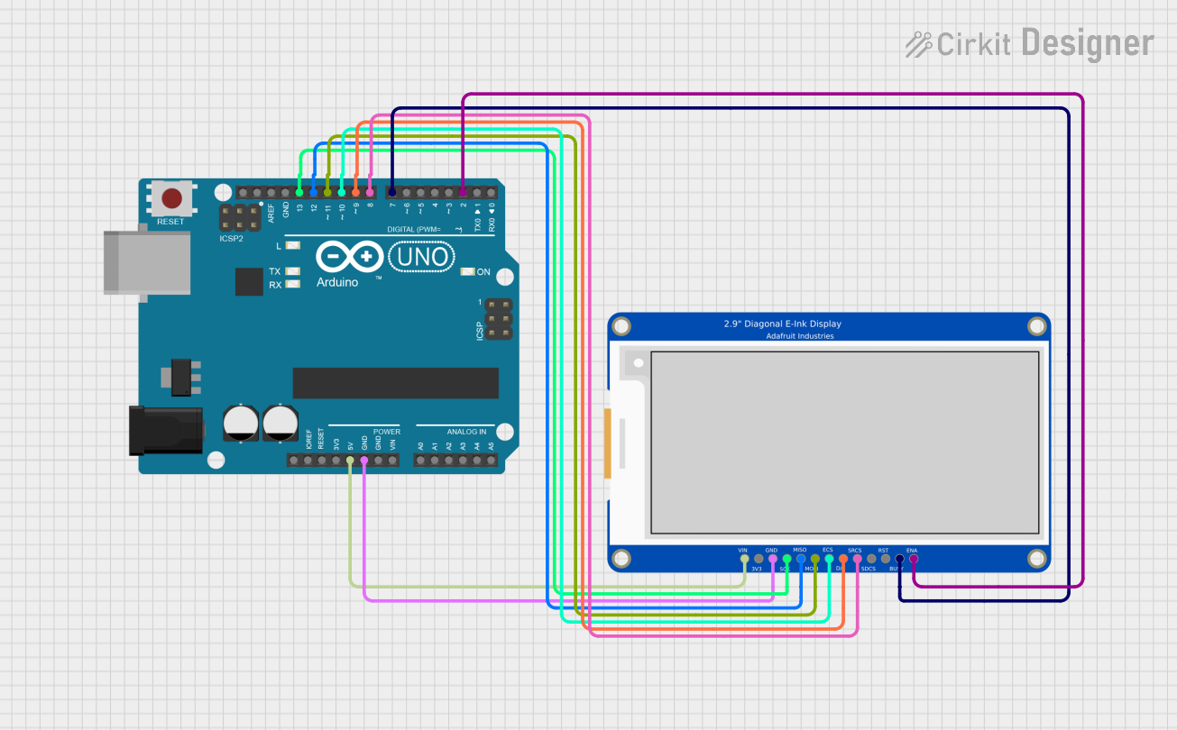
Example: Connecting the Greycode Board to an Arduino UNO
Below is an example of how to connect the Greycode Board to an Arduino UNO and read the Grey code output:
Circuit Connections
- Connect
VCCto the 5V pin on the Arduino. - Connect
GNDto the GND pin on the Arduino. - Connect
OUT0,OUT1,OUT2, andOUT3to Arduino digital pins 2, 3, 4, and 5, respectively. - Connect the
ENpin to Arduino digital pin 6.
Arduino Code
// Define pins for Greycode Board outputs
const int OUT0 = 2; // Grey code bit 0 (LSB)
const int OUT1 = 3; // Grey code bit 1
const int OUT2 = 4; // Grey code bit 2
const int OUT3 = 5; // Grey code bit 3 (MSB)
const int EN = 6;   // Enable pin

void setup() {
  // Initialize serial communication for debugging
  Serial.begin(9600);

  // Set Greycode Board pins as inputs
  pinMode(OUT0, INPUT);
  pinMode(OUT1, INPUT);
  pinMode(OUT2, INPUT);
  pinMode(OUT3, INPUT);

  // Set enable pin as output and activate the board
  pinMode(EN, OUTPUT);
  digitalWrite(EN, HIGH); // Enable the Greycode Board
}

void loop() {
  // Read Grey code output bits
  int greyCode0 = digitalRead(OUT0);
  int greyCode1 = digitalRead(OUT1);
  int greyCode2 = digitalRead(OUT2);
  int greyCode3 = digitalRead(OUT3);

  // Combine bits into a single Grey code value
  int greyCodeValue = (greyCode3 << 3) | (greyCode2 << 2) |
                      (greyCode1 << 1) | greyCode0;

  // Print the Grey code value to the serial monitor
  Serial.print("Grey Code Value: ");
  Serial.println(greyCodeValue);

  // Add a small delay for stability
  delay(500);
}
Troubleshooting and FAQs
Common Issues and Solutions
No Output from the Board
- Cause: The
ENpin is not set HIGH. - Solution: Ensure the
ENpin is connected to a HIGH signal to activate the board.
- Cause: The
Incorrect Grey Code Values
- Cause: Loose or incorrect connections to the output pins.
- Solution: Double-check all connections and ensure the output pins are properly connected to the microcontroller.
Board Not Powering On
- Cause: Insufficient or unstable power supply.
- Solution: Verify that the
VCCpin is receiving a stable 5V DC supply.
Interference in Output Signals
- Cause: Noise in the clock signal or power supply.
- Solution: Use decoupling capacitors near the power pins and ensure the clock signal is clean.
FAQs
Q: Can the Greycode Board operate at voltages other than 5V?
A: No, the board is designed to operate at 5V DC only. Using other voltages may damage the board.Q: Is the
CLKpin mandatory for operation?
A: No, theCLKpin is optional and only required for applications needing synchronized Grey code transitions.Q: Can I use this board with microcontrollers other than Arduino?
A: Yes, the board can be used with any microcontroller that supports 5V logic levels.Q: How many Grey code bits does the board output?
A: The board outputs a 4-bit Grey code value.
This documentation provides all the necessary details to effectively use the Arduino Greycode Board in your projects.