How to Use SN65HVD75DR: Examples, Pinouts, and Specs
Introduction
The SN65HVD75DR is a high-speed Controller Area Network (CAN) transceiver manufactured by Texas Instruments. It is designed to facilitate robust and reliable communication in automotive and industrial applications. With support for data rates up to 1 Mbps, this transceiver is ideal for high-speed CAN networks. Its low power consumption makes it suitable for battery-operated devices, while its robust design ensures reliable operation in harsh environments. Additionally, the SN65HVD75DR offers excellent electromagnetic compatibility (EMC), making it a preferred choice for noise-sensitive applications.
Explore Projects Built with SN65HVD75DR

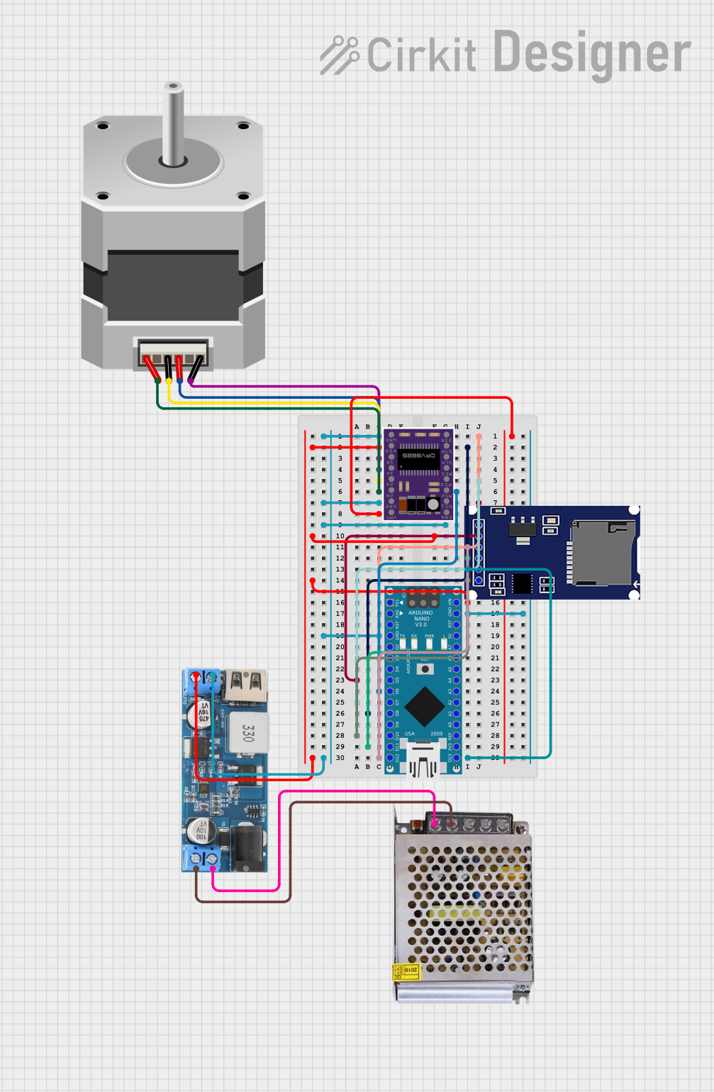


Explore Projects Built with SN65HVD75DR
Common Applications
- Automotive systems (e.g., engine control units, body electronics)
- Industrial automation and control
- Building automation (e.g., HVAC systems)
- Battery-powered devices
- Robotics and embedded systems
Technical Specifications
Key Technical Details
| Parameter | Value |
|---|---|
| Supply Voltage (Vcc) | 4.5 V to 5.5 V |
| Data Rate | Up to 1 Mbps |
| Bus Voltage Range | -7 V to +12 V |
| Operating Temperature | -40°C to +125°C |
| Standby Current | 1 µA (typical) |
| Driver Output Voltage | -7 V to +12 V |
| Receiver Input Resistance | 30 kΩ (minimum) |
| Package Type | SOIC-8 (Small Outline Integrated Circuit) |
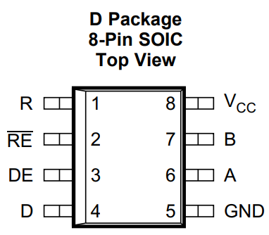
Pin Configuration and Descriptions
The SN65HVD75DR is an 8-pin device with the following pinout:
| Pin Number | Pin Name | Description |
|---|---|---|
| 1 | CANH | High-level CAN bus line |
| 2 | CANL | Low-level CAN bus line |
| 3 | GND | Ground |
| 4 | Vcc | Supply voltage (4.5 V to 5.5 V) |
| 5 | Rs | Slope control and standby mode selection |
| 6 | NC | No connection (leave unconnected) |
| 7 | R | Receiver output (RXD) |
| 8 | D | Driver input (TXD) |
Usage Instructions
How to Use the SN65HVD75DR in a Circuit
- Power Supply: Connect the Vcc pin to a 5 V regulated power supply and the GND pin to the ground of the circuit.
- CAN Bus Lines: Connect the CANH and CANL pins to the respective high and low lines of the CAN bus.
- Driver Input (TXD): Connect the D pin to the microcontroller's CAN TX pin.
- Receiver Output (RXD): Connect the R pin to the microcontroller's CAN RX pin.
- Slope Control: Use the Rs pin to control the slew rate of the driver. Connect a resistor to ground for slope control or leave it floating for high-speed mode. To enable standby mode, pull the Rs pin high.
Important Considerations
- Termination Resistors: Ensure that the CAN bus is properly terminated with 120 Ω resistors at both ends to prevent signal reflections.
- EMC Design: Use proper PCB layout techniques, such as short traces and decoupling capacitors, to minimize noise and improve EMC performance.
- Standby Mode: To reduce power consumption, use the Rs pin to enable standby mode when the transceiver is not in use.
Example Code for Arduino UNO
The following example demonstrates how to use the SN65HVD75DR with an Arduino UNO for basic CAN communication. This example assumes the use of an external CAN controller (e.g., MCP2515) connected to the SN65HVD75DR.
#include <SPI.h>
#include <mcp_can.h>

// Define the SPI CS pin for the MCP2515 CAN controller
#define CAN_CS_PIN 10

// Initialize the MCP_CAN object
MCP_CAN CAN(CAN_CS_PIN);

void setup() {
  Serial.begin(115200); // Initialize serial communication for debugging
  while (!Serial);

  // Initialize the CAN controller at 500 kbps
  if (CAN.begin(MCP_ANY, CAN_500KBPS, MCP_8MHZ) == CAN_OK) {
    Serial.println("CAN initialized successfully!");
  } else {
    Serial.println("CAN initialization failed!");
    while (1);
  }

  // Set the CAN controller to normal mode
  CAN.setMode(MCP_NORMAL);
  Serial.println("CAN controller set to normal mode.");
}

void loop() {
  // Example: Send a CAN message with ID 0x100
  byte data[8] = {0x01, 0x02, 0x03, 0x04, 0x05, 0x06, 0x07, 0x08};
  if (CAN.sendMsgBuf(0x100, 0, 8, data) == CAN_OK) {
    Serial.println("Message sent successfully!");
  } else {
    Serial.println("Error sending message.");
  }

  delay(1000); // Wait 1 second before sending the next message
}
Troubleshooting and FAQs
Common Issues and Solutions
No Communication on the CAN Bus
- Ensure that the CAN bus is properly terminated with 120 Ω resistors at both ends.
- Verify that the Vcc and GND pins are correctly connected to the power supply.
- Check the connections between the microcontroller, CAN controller, and SN65HVD75DR.
High Power Consumption
- Ensure that the Rs pin is configured correctly. Pull the Rs pin high to enable standby mode when the transceiver is not in use.
Signal Distortion or Noise
- Use proper PCB layout techniques, such as keeping traces short and adding decoupling capacitors near the Vcc pin.
- Verify that the CANH and CANL lines are twisted pair cables to reduce electromagnetic interference.
Device Overheating
- Check for short circuits or incorrect connections.
- Ensure that the supply voltage does not exceed the maximum rating of 5.5 V.
FAQs
Q: Can the SN65HVD75DR operate at 3.3 V?
A: No, the SN65HVD75DR requires a supply voltage between 4.5 V and 5.5 V. For 3.3 V systems, consider using a transceiver designed for lower voltage operation.
Q: How do I enable standby mode?
A: Pull the Rs pin high to enable standby mode, which reduces power consumption to a typical value of 1 µA.
Q: What is the maximum cable length for the CAN bus?
A: The maximum cable length depends on the data rate. For a 1 Mbps data rate, the maximum recommended length is approximately 40 meters. For lower data rates, longer cable lengths are possible.