How to Use MD20 CYTRON MOTOR DRIVER: Examples, Pinouts, and Specs
Introduction
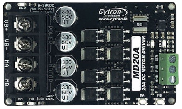
The MD20 Cytron Motor Driver is a versatile and powerful motor controller designed for DC motors. It is widely used in robotics, automation projects, and educational platforms to control the speed and direction of motors. The driver is capable of handling a substantial current and voltage, making it suitable for a variety of applications.
Explore Projects Built with MD20 CYTRON MOTOR DRIVER


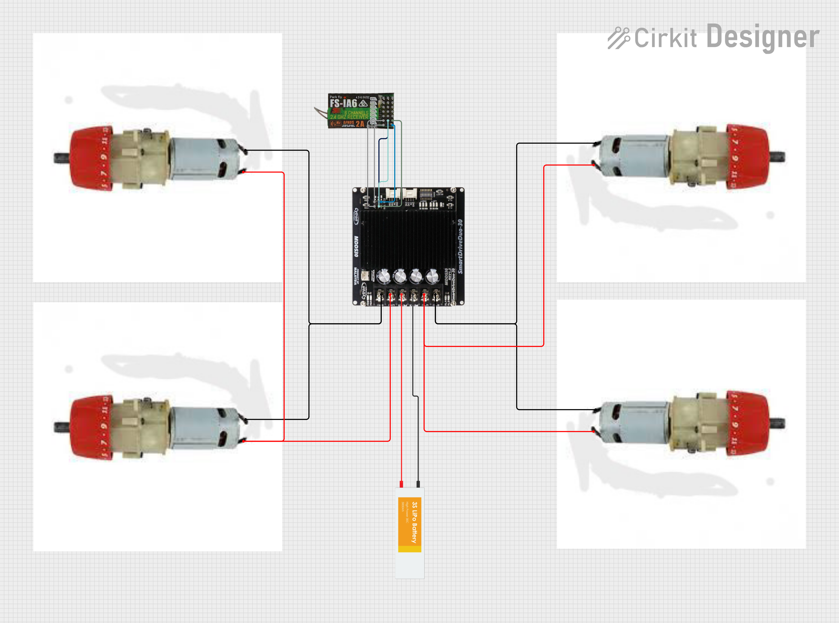
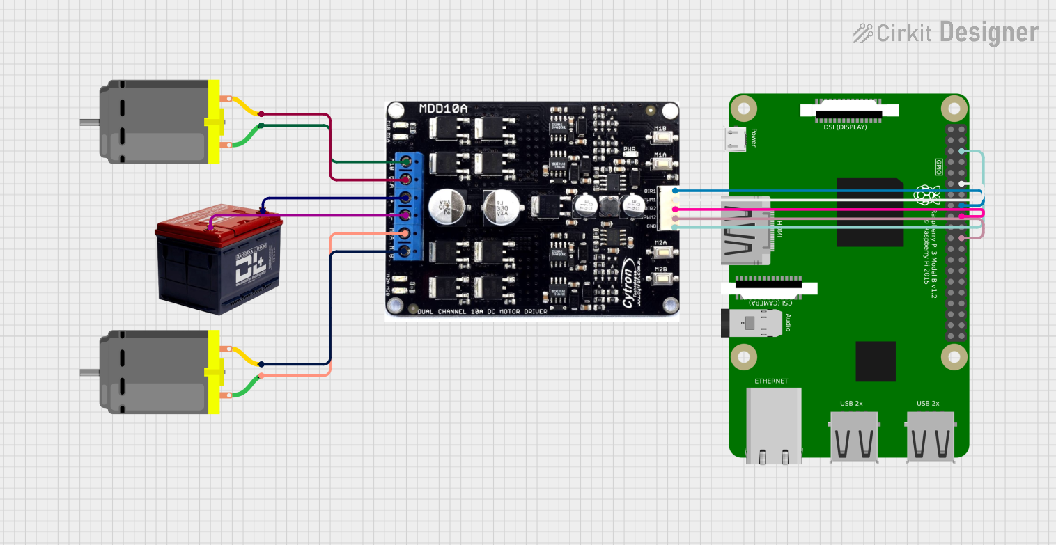
Explore Projects Built with MD20 CYTRON MOTOR DRIVER
Common Applications and Use Cases
- Robotics: Driving wheels or tracks
- Automation: Controlling conveyor belts or machinery
- Educational Projects: Teaching motor control principles
- Hobby Projects: Remote-controlled vehicles or boats
Technical Specifications
Key Technical Details
- Operating Voltage: 6V to 30V
- Continuous Current: Up to 20A
- Peak Current: 30A for a few seconds
- Logic Voltage: 3.3V to 5V (5V is typical for Arduino compatibility)
- PWM Frequency: Up to 20kHz (recommended for silent operation)
- Control Signal: PWM and DIR (Direction)
Pin Configuration and Descriptions
| Pin Name | Description |
|---|---|
| Vmotor | Motor power supply (6V to 30V) |
| GND | Ground connection |
| PWM | Pulse Width Modulation input for speed control |
| DIR | Direction control input (Logic High/Low) |
| EN | Enable pin (Active High) |
| AN | Analog input for speed control (alternative to PWM) |
| LIMIT | Current limiting sensitivity adjustment |
Usage Instructions
How to Use the Component in a Circuit
Power Connections:
- Connect the motor's power supply to the
VmotorandGNDpins. - Ensure the power supply is within the specified voltage range.
- Connect the motor's power supply to the
Motor Connections:
- Connect the two leads of the DC motor to the output terminals of the MD20.
Control Connections:
- Connect the
PWMpin to a PWM-capable pin on the Arduino for speed control. - Connect the
DIRpin to a digital output on the Arduino to set the motor's direction. - Optionally, connect the
ENpin to a digital output for enabling/disabling the motor driver.
- Connect the
Arduino Connections:
- Connect the Arduino GND to the MD20 GND to establish a common ground.
Important Considerations and Best Practices
- Always ensure the power supply is disconnected before making any connections.
- Use appropriate gauge wires to handle the current drawn by the motor.
- Do not exceed the voltage and current ratings to prevent damage.
- Use a flyback diode across the motor terminals if driving inductive loads to protect against voltage spikes.
- Implement proper heat dissipation measures if operating the driver near its maximum ratings.
Example Arduino Code
// Define the connections
const int pwmPin = 3; // PWM input for speed control
const int dirPin = 4; // Direction control input

void setup() {
  pinMode(pwmPin, OUTPUT);
  pinMode(dirPin, OUTPUT);
}

void loop() {
  // Set motor direction to forward
  digitalWrite(dirPin, HIGH);
  // Set motor speed (0 to 255)
  analogWrite(pwmPin, 128); // 50% duty cycle for half speed
  delay(2000); // Run for 2 seconds

  // Change direction to reverse
  digitalWrite(dirPin, LOW);
  // Keep the same speed
  delay(2000); // Run for 2 seconds

  // Stop the motor
  analogWrite(pwmPin, 0);
  delay(1000); // Stop for 1 second
}
Troubleshooting and FAQs
Common Issues Users Might Face
- Motor not running: Check power supply connections and ensure the enable pin is set high if used.
- Motor running only in one direction: Verify the DIR pin connection and signal.
- Overheating: Ensure proper heat dissipation and check if the current exceeds the rated limit.
Solutions and Tips for Troubleshooting
- Double-check all connections according to the pin configuration.
- Use a multimeter to verify the presence of voltage at the motor terminals.
- Test the PWM and DIR signals from the Arduino using an oscilloscope or logic analyzer.
- If the motor driver overheats, add a heatsink or improve airflow around the component.
FAQs
Q: Can I control two motors with one MD20 driver? A: No, the MD20 is designed to control one motor. For two motors, you will need two MD20 drivers.
Q: What should I do if the motor driver gets hot during operation? A: Ensure that the current draw is within the limit and consider adding a heatsink or fan for cooling.
Q: Can I use the MD20 with a microcontroller other than Arduino? A: Yes, as long as the microcontroller can provide the appropriate PWM and direction signals within the logic voltage range.
Remember, safety first! Always follow proper electrical safety procedures when working with electronic components.