How to Use GPS GSM GPRS module: Examples, Pinouts, and Specs
Introduction
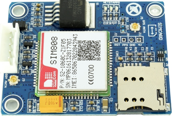
The SIM808 is a multifunctional module that integrates GPS, GSM, and GPRS functionalities into a single compact unit. It is designed to provide location tracking, mobile communication, and data transmission capabilities, making it ideal for a wide range of applications. The module is widely used in IoT devices, vehicle tracking systems, remote monitoring, and other projects requiring cellular connectivity and GPS functionality.
Explore Projects Built with GPS GSM GPRS module
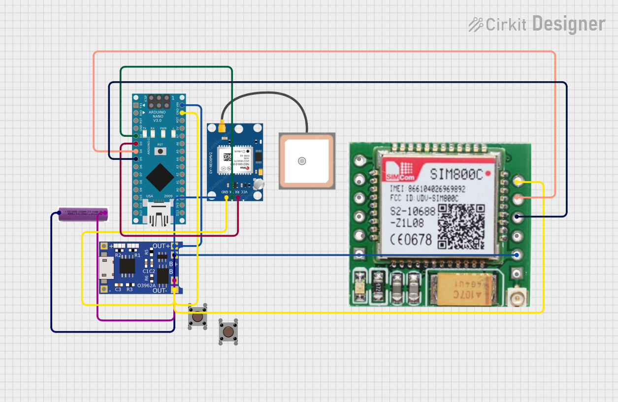
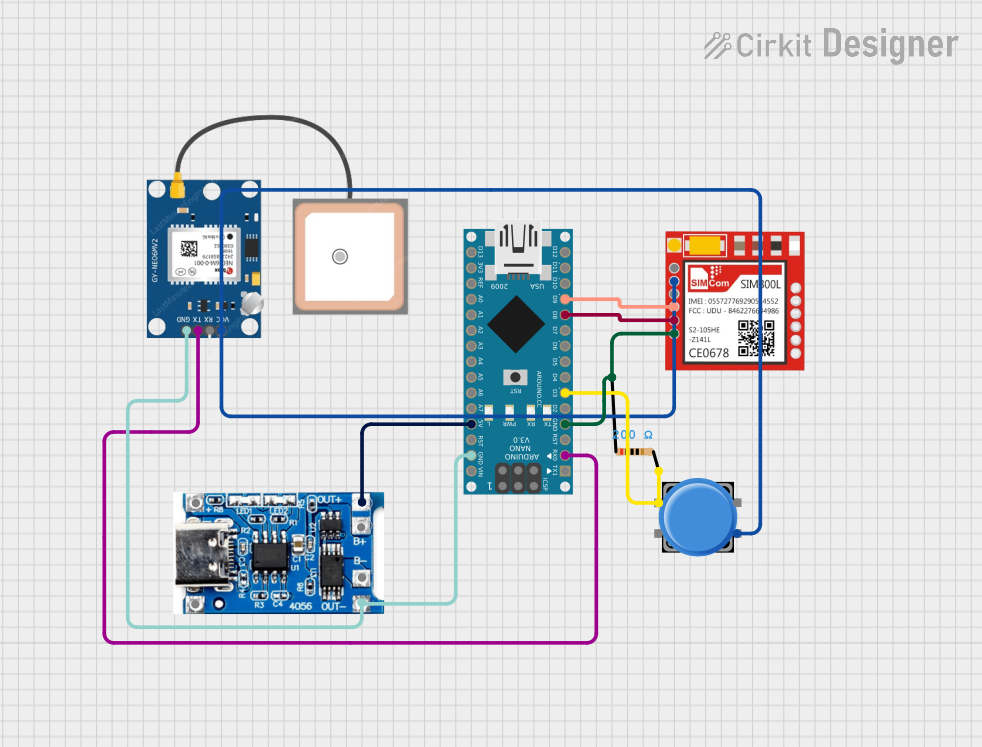
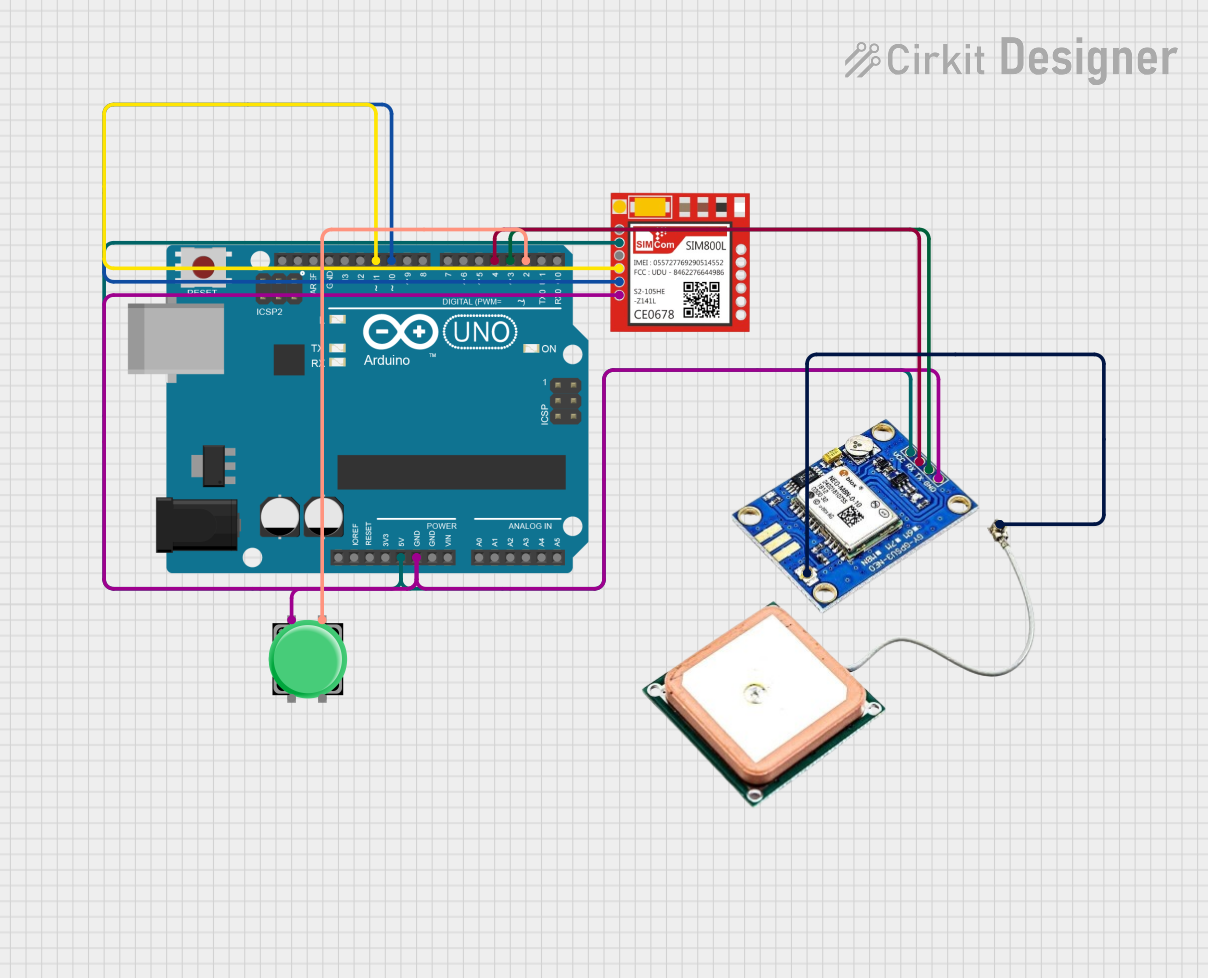

Explore Projects Built with GPS GSM GPRS module
Common Applications and Use Cases
- Vehicle tracking and fleet management
- IoT devices requiring cellular connectivity
- Remote monitoring and control systems
- Personal tracking devices
- Emergency location services
- Smart agriculture and environmental monitoring
Technical Specifications
Key Technical Details
| Parameter | Value |
|---|---|
| Manufacturer | SIMCom |
| Part Number | SIM808 |
| Operating Voltage | 3.4V to 4.4V |
| Operating Current | Idle: ~1mA, GSM Transmission: ~2A (peak) |
| GPS Sensitivity | -165 dBm |
| GSM Frequency Bands | Quad-band: 850/900/1800/1900 MHz |
| GPRS Connectivity | Class 12 |
| GPS Position Accuracy | < 2.5 meters |
| Communication Interface | UART, AT Commands |
| Operating Temperature | -40°C to +85°C |
| Dimensions | 24mm x 24mm x 3mm |
Pin Configuration and Descriptions
The SIM808 module typically comes with a breakout board or pin headers for easy integration. Below is the pin configuration:
| Pin Number | Pin Name | Description |
|---|---|---|
| 1 | VCC | Power supply input (3.4V to 4.4V). |
| 2 | GND | Ground connection. |
| 3 | TXD | UART Transmit pin (connect to RX of microcontroller). |
| 4 | RXD | UART Receive pin (connect to TX of microcontroller). |
| 5 | NETLIGHT | Network status indicator (blinks to indicate GSM/GPRS status). |
| 6 | PWRKEY | Power-on key (active low, hold for 1 second to power on/off the module). |
| 7 | GPS_TXD | GPS UART Transmit pin (connect to RX of microcontroller for GPS data). |
| 8 | GPS_RXD | GPS UART Receive pin (connect to TX of microcontroller for GPS commands). |
| 9 | ANT_GSM | GSM antenna connection. |
| 10 | ANT_GPS | GPS antenna connection. |
Usage Instructions
How to Use the SIM808 Module in a Circuit
- Power Supply: Ensure a stable power supply of 3.7V to 4.2V with sufficient current (at least 2A peak) to handle GSM transmission.
- Antenna Connections: Connect a GSM antenna to the
ANT_GSMpin and a GPS antenna to theANT_GPSpin for proper signal reception. - UART Communication: Connect the
TXDandRXDpins to the corresponding UART pins of your microcontroller (e.g., Arduino UNO). - Power On: Use the
PWRKEYpin to turn on the module. Hold the pin low for at least 1 second to power on the module. - AT Commands: Communicate with the module using AT commands via UART to configure GSM, GPRS, and GPS functionalities.
Important Considerations and Best Practices
- Use decoupling capacitors near the power supply pins to reduce noise and voltage fluctuations.
- Ensure proper grounding to avoid communication issues.
- Place the GSM and GPS antennas away from each other to minimize interference.
- Use a level shifter if interfacing with a 5V microcontroller, as the SIM808 operates at 3.3V logic levels.
Example: Connecting SIM808 to Arduino UNO
Below is an example of how to use the SIM808 module with an Arduino UNO to send an SMS and retrieve GPS coordinates.
Circuit Connections
| SIM808 Pin | Arduino Pin |
|---|---|
| VCC | 5V (via a 3.7V regulator) |
| GND | GND |
| TXD | Pin 10 (RX) |
| RXD | Pin 11 (TX) |
| PWRKEY | Digital Pin 9 (optional) |
Arduino Code
#include <SoftwareSerial.h>

// Define SIM808 RX and TX pins
SoftwareSerial sim808(10, 11); // RX = Pin 10, TX = Pin 11

void setup() {
  Serial.begin(9600);          // Initialize Serial Monitor
  sim808.begin(9600);          // Initialize SIM808 communication
  pinMode(9, OUTPUT);          // PWRKEY pin
  digitalWrite(9, LOW);        // Power on the SIM808 module
  delay(1000);                 // Wait for the module to initialize
  digitalWrite(9, HIGH);

  // Send an SMS
  sendSMS("+1234567890", "Hello from SIM808!");
}

void loop() {
  // Continuously read GPS data
  if (sim808.available()) {
    Serial.write(sim808.read());
  }
}

void sendSMS(const char* phoneNumber, const char* message) {
  sim808.println("AT+CMGF=1"); // Set SMS mode to text
  delay(100);
  sim808.print("AT+CMGS=\"");
  sim808.print(phoneNumber);
  sim808.println("\"");
  delay(100);
  sim808.print(message);
  delay(100);
  sim808.write(26); // Send Ctrl+Z to send the SMS
  delay(1000);
}
Troubleshooting and FAQs
Common Issues and Solutions
Module Not Powering On
- Ensure the power supply provides sufficient current (at least 2A peak).
- Check the
PWRKEYpin connection and hold it low for at least 1 second.
No GSM Network Connection
- Verify the GSM antenna is properly connected.
- Check the SIM card for proper insertion and activation.
- Use the
AT+CSQcommand to check signal strength (higher than 10 is recommended).
GPS Not Receiving Data
- Ensure the GPS antenna is connected and placed in an open area with a clear view of the sky.
- Use the
AT+CGNSPWR=1command to enable GPS functionality.
UART Communication Issues
- Verify the baud rate matches between the SIM808 and the microcontroller.
- Check for proper wiring of the
TXDandRXDpins.
FAQs
Q: Can the SIM808 module work with a 5V microcontroller?
A: Yes, but you need a level shifter for the UART pins, as the SIM808 operates at 3.3V logic levels.
Q: How do I check the module's firmware version?
A: Use the AT+GMR command to retrieve the firmware version.
Q: Can I use the SIM808 for 3G or 4G networks?
A: No, the SIM808 only supports GSM (2G) networks. Ensure your region still supports 2G connectivity.
Q: How do I enable GPRS for data transmission?
A: Use the following AT commands:
AT+SAPBR=3,1,"CONTYPE","GPRS"AT+SAPBR=3,1,"APN","<Your_APN>"AT+SAPBR=1,1
This will configure and enable GPRS connectivity.