How to Use Energy Meter: Examples, Pinouts, and Specs
Introduction
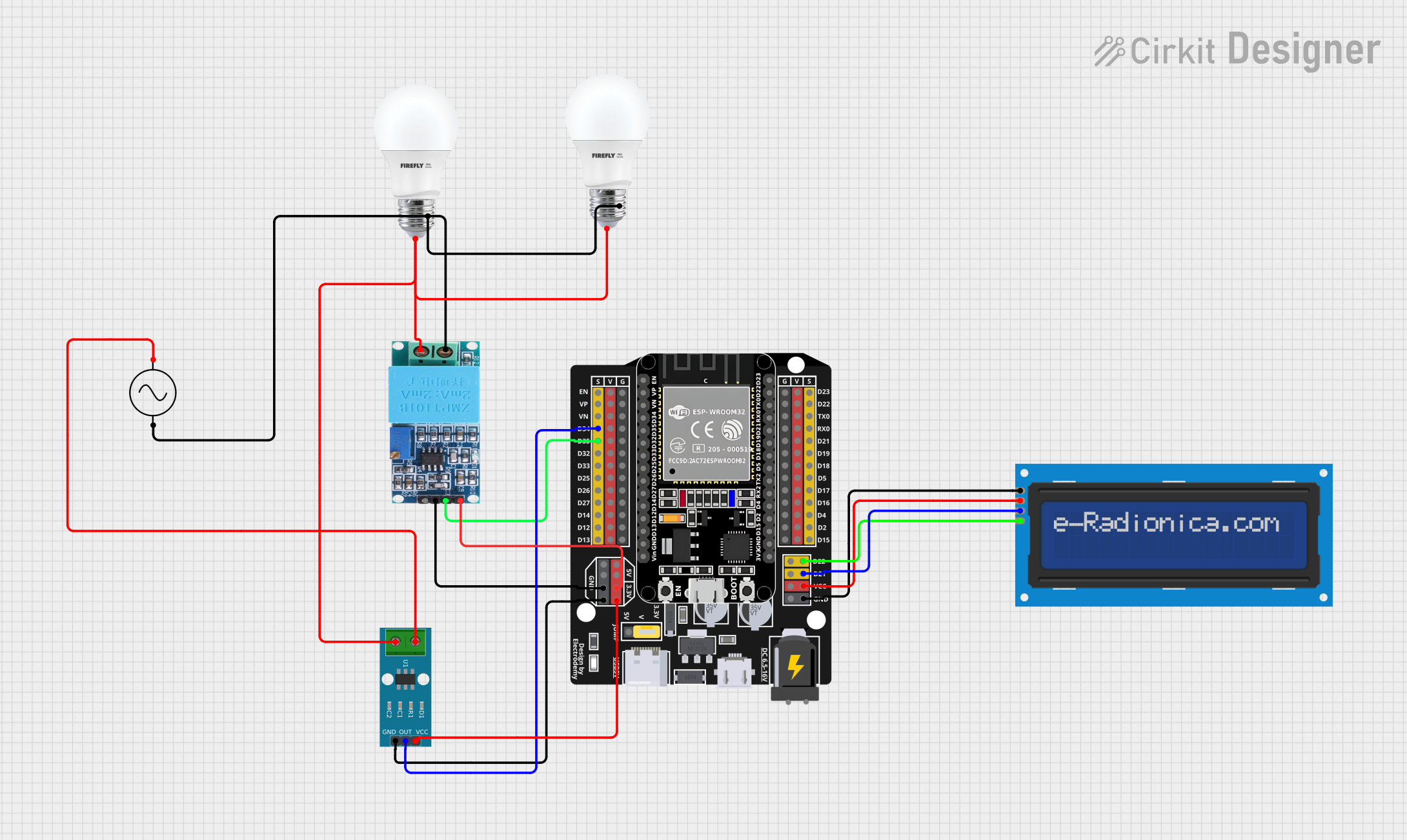
An Energy Meter is a device used to measure the amount of electrical energy consumed by a residence, business, or an electrically powered device. It provides accurate readings of energy usage, typically in kilowatt-hours (kWh), and is essential for monitoring and managing electricity consumption. Energy meters are widely used in residential, commercial, and industrial applications to track energy usage for billing, energy efficiency, and load management purposes.
Explore Projects Built with Energy Meter
Explore Projects Built with Energy Meter
Common Applications and Use Cases
- Residential Energy Monitoring: Tracking household electricity consumption for billing and energy-saving purposes.
- Industrial and Commercial Use: Monitoring energy usage in factories, offices, and commercial buildings.
- Renewable Energy Systems: Measuring energy generated and consumed in solar or wind power systems.
- Smart Home Systems: Integrating with IoT devices for real-time energy monitoring and automation.
- Load Management: Identifying high-energy-consuming devices to optimize energy usage.
Technical Specifications
Below are the key technical details of a typical energy meter:
| Parameter | Specification |
|---|---|
| Voltage Range | 110V - 240V AC |
| Current Range | 0A - 100A |
| Frequency | 50Hz / 60Hz |
| Power Measurement Range | 0W - 22kW |
| Accuracy Class | ±1% |
| Communication Protocol | RS485, Modbus, or IoT (Wi-Fi, Zigbee) |
| Display Type | LCD/LED |
| Power Supply | Self-powered or external (e.g., 5V DC) |
| Operating Temperature | -20°C to 60°C |
| Dimensions | Varies by model (e.g., 100mm x 70mm x 50mm) |
Pin Configuration and Descriptions
The pin configuration of an energy meter depends on its type (e.g., single-phase or three-phase). Below is an example of a single-phase energy meter:
| Pin Name | Description |
|---|---|
| L (Line) | Connects to the live wire of the AC mains supply. |
| N (Neutral) | Connects to the neutral wire of the AC mains supply. |
| COM | Communication pin for RS485/Modbus (if applicable). |
| GND | Ground connection for communication or power. |
| VCC | External power supply input (if required). |
For three-phase energy meters, additional pins for Phase 2 (L2) and Phase 3 (L3) are included.
Usage Instructions
How to Use the Energy Meter in a Circuit
Wiring:
- Connect the L (Line) and N (Neutral) terminals to the AC mains supply.
- If the meter supports communication, connect the COM and GND pins to the appropriate interface (e.g., RS485 or IoT module).
- For external power supply models, connect the VCC and GND pins to a 5V DC power source.
Load Connection:
- Connect the load (e.g., appliances or devices) to the output terminals of the energy meter.
Configuration:
- If the energy meter supports communication protocols like Modbus, configure the communication settings (e.g., baud rate, device ID) using the provided software or hardware interface.
Reading Energy Data:
- Use the built-in display to view energy consumption in real-time.
- For advanced models, retrieve data via communication protocols or IoT platforms.
Important Considerations and Best Practices
- Ensure the energy meter's voltage and current ratings match the application requirements.
- Avoid overloading the meter beyond its rated current and power capacity.
- For accurate readings, install the meter in a location with minimal electrical noise and stable temperature conditions.
- If using a communication interface, ensure proper grounding and shielding of communication cables to prevent interference.
- Regularly calibrate the energy meter if required, especially in industrial applications.
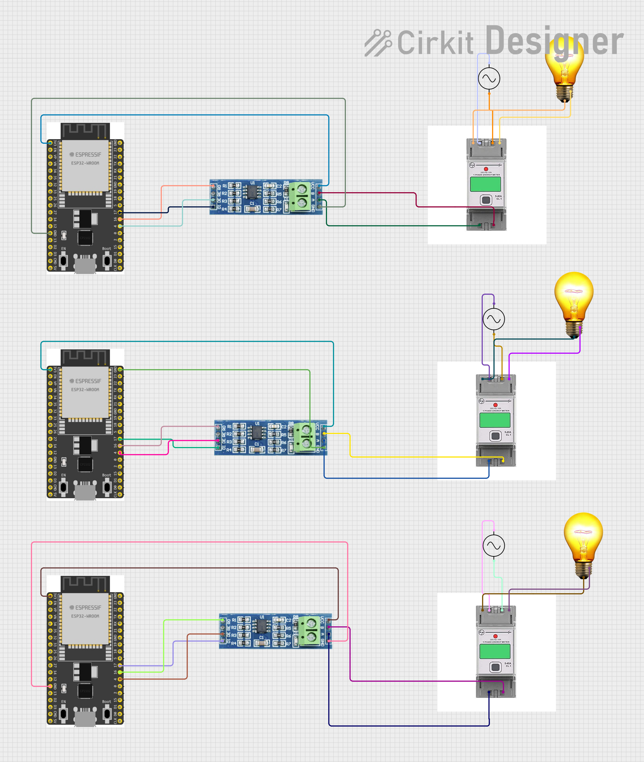
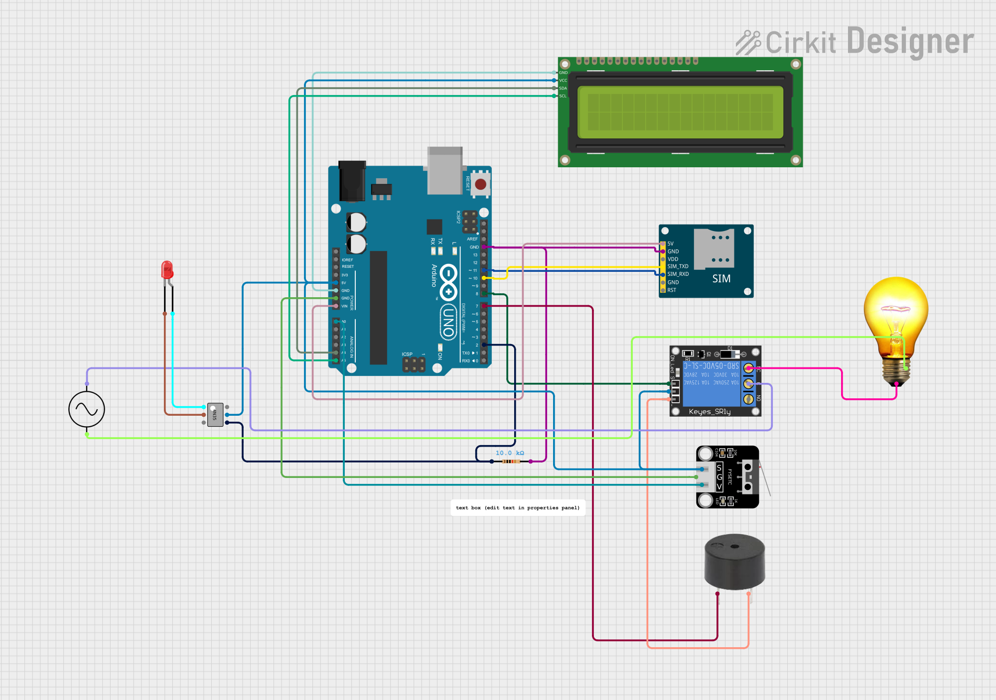
Example: Connecting an Energy Meter to an Arduino UNO
If the energy meter supports Modbus communication, you can connect it to an Arduino UNO for data logging. Below is an example code snippet:
#include <ModbusMaster.h>

// Create an instance of the ModbusMaster library
ModbusMaster node;

// Define the RS485 communication pins
#define RE_PIN 2  // Receiver Enable pin
#define DE_PIN 3  // Driver Enable pin

void preTransmission() {
  digitalWrite(RE_PIN, HIGH); // Enable transmission
  digitalWrite(DE_PIN, HIGH);
}

void postTransmission() {
  digitalWrite(RE_PIN, LOW);  // Disable transmission
  digitalWrite(DE_PIN, LOW);
}

void setup() {
  // Initialize serial communication
  Serial.begin(9600);
  Serial.println("Energy Meter Reading");

  // Initialize RS485 communication
  pinMode(RE_PIN, OUTPUT);
  pinMode(DE_PIN, OUTPUT);
  digitalWrite(RE_PIN, LOW);
  digitalWrite(DE_PIN, LOW);

  // Configure Modbus communication
  node.begin(1, Serial); // Set Modbus ID to 1
  node.preTransmission(preTransmission);
  node.postTransmission(postTransmission);
}

void loop() {
  uint8_t result;
  uint16_t data;

  // Read energy consumption (e.g., register 0x0000)
  result = node.readInputRegisters(0x0000, 1);

  if (result == node.ku8MBSuccess) {
    data = node.getResponseBuffer(0);
    Serial.print("Energy Consumption: ");
    Serial.print(data);
    Serial.println(" kWh");
  } else {
    Serial.println("Error reading energy meter");
  }

  delay(1000); // Wait 1 second before the next reading
}
Notes:
- Use an RS485-to-TTL converter to connect the energy meter to the Arduino UNO.
- Modify the Modbus ID and register address based on your energy meter's documentation.
Troubleshooting and FAQs
Common Issues and Solutions
No Display or Power:
- Cause: Incorrect wiring or insufficient power supply.
- Solution: Verify the wiring connections and ensure the meter is receiving the correct voltage.
Inaccurate Readings:
- Cause: Electrical noise, incorrect installation, or calibration issues.
- Solution: Install the meter in a noise-free environment and recalibrate if necessary.
Communication Failure:
- Cause: Incorrect communication settings or wiring issues.
- Solution: Check the baud rate, device ID, and wiring of the communication interface.
Overload Protection Triggered:
- Cause: Load exceeds the meter's rated capacity.
- Solution: Reduce the load to within the meter's rated limits.
FAQs
Q1: Can the energy meter measure DC power?
A1: Most energy meters are designed for AC power. For DC power measurement, use a DC energy meter.
Q2: How do I reset the energy meter readings?
A2: Refer to the user manual for reset instructions. Some meters have a physical reset button, while others require software commands.
Q3: Can I use the energy meter outdoors?
A3: Only if the meter is rated for outdoor use (e.g., IP65 or higher). Otherwise, install it in a weatherproof enclosure.
Q4: What is the lifespan of an energy meter?
A4: The typical lifespan is 10-15 years, depending on usage and environmental conditions. Regular maintenance can extend its life.