How to Use H bridge : Examples, Pinouts, and Specs
Introduction
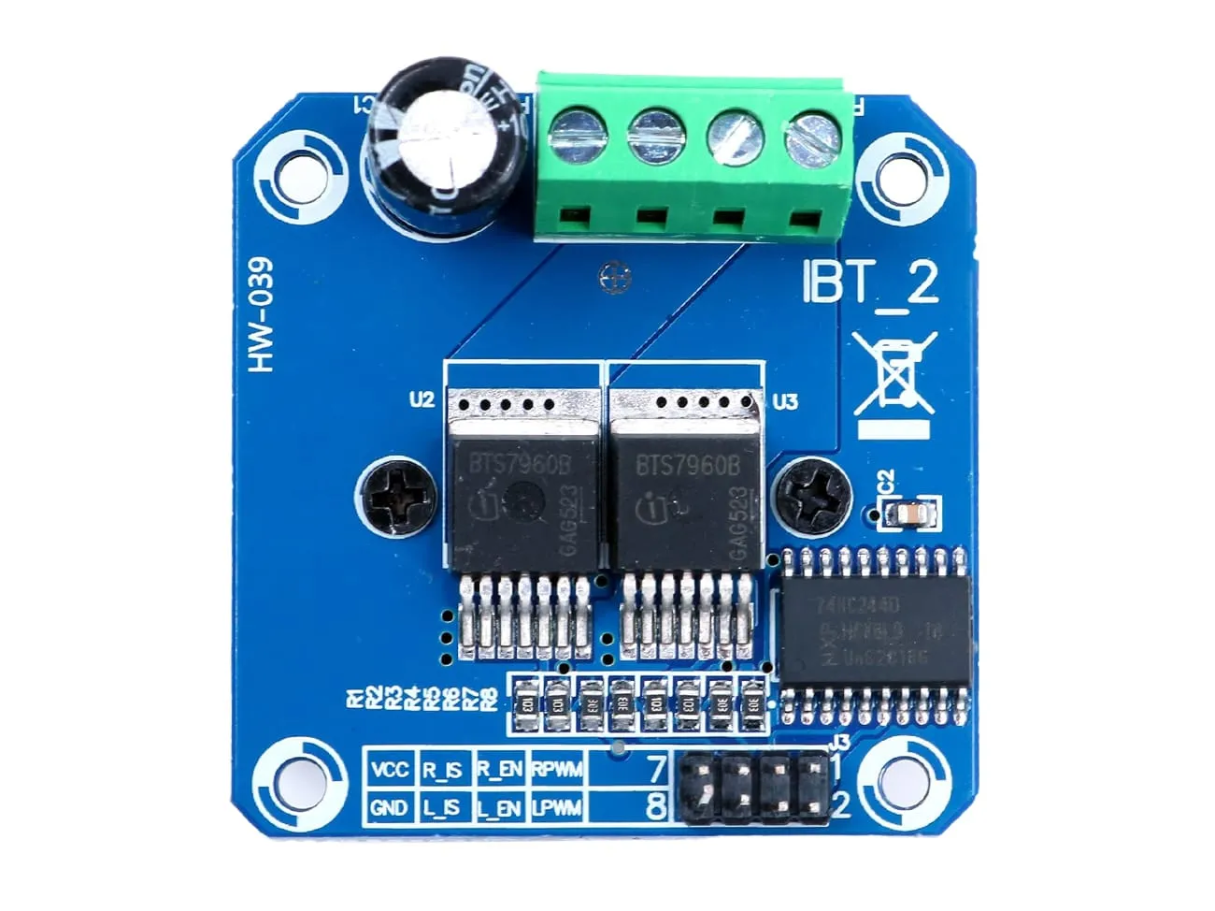
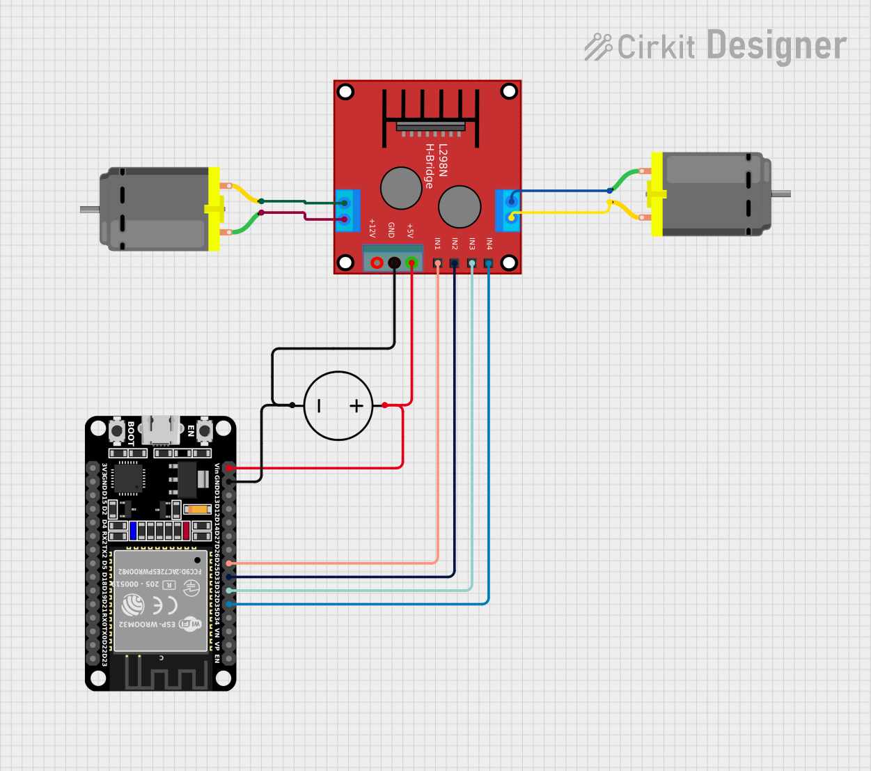
The H Bridge (Manufacturer Part ID: MTD-02669) is an electronic circuit designed to control the direction of current flow through a load, such as a DC motor. By enabling bidirectional current flow, the H Bridge allows for precise control of motor direction and speed. This component is widely used in robotics, motor control systems, and other applications requiring reversible motor operation.
Explore Projects Built with H bridge
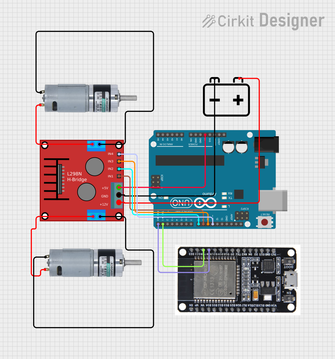
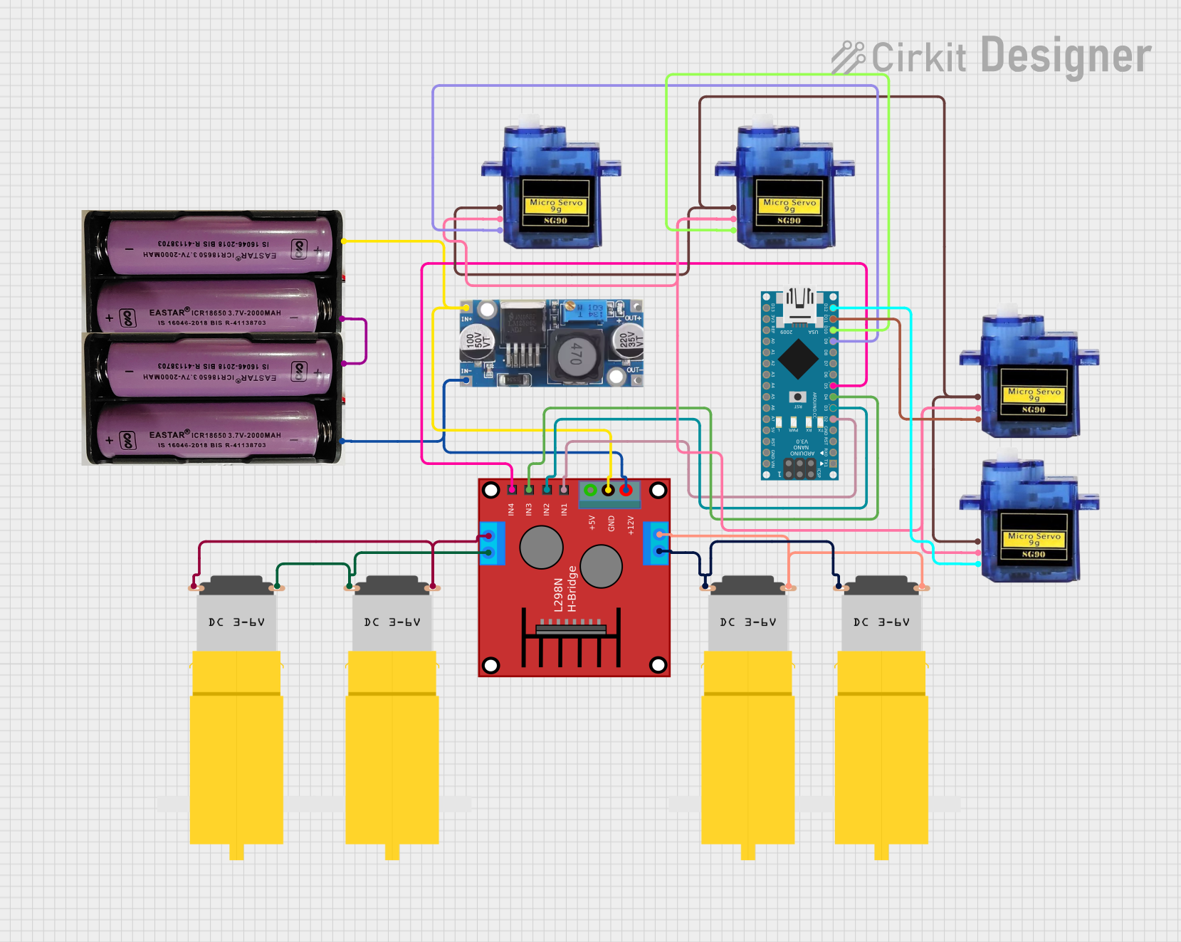
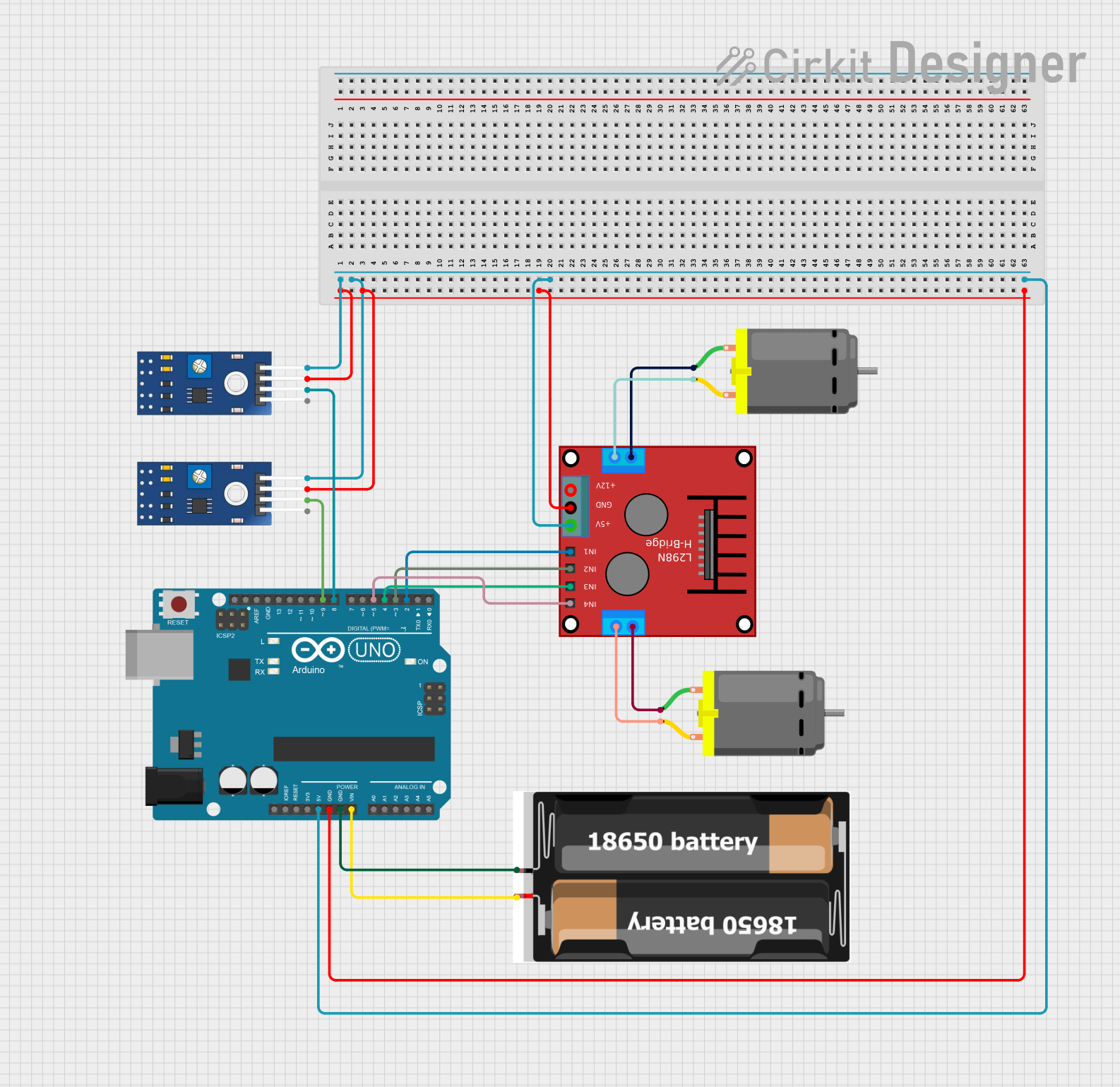
Explore Projects Built with H bridge
Common Applications and Use Cases
- DC motor control for robotics and automation
- Stepper motor driving
- Bidirectional control of actuators
- Power inverters and switching circuits
- Educational projects involving motor control with microcontrollers (e.g., Arduino)
Technical Specifications
The following table outlines the key technical details of the MTD-02669 H Bridge:
| Parameter | Value |
|---|---|
| Operating Voltage | 5V to 36V |
| Maximum Current | 2A per channel (continuous) |
| Peak Current | 3A per channel (short duration) |
| Logic Input Voltage | 3.3V to 5V |
| Switching Frequency | Up to 20 kHz |
| Thermal Shutdown | Yes |
| Dimensions | 25mm x 30mm x 10mm |
Pin Configuration and Descriptions
The MTD-02669 H Bridge typically has the following pinout:
| Pin | Name | Description |
|---|---|---|
| 1 | VCC | Power supply input (5V to 36V). Connect to the positive terminal of the power source. |
| 2 | GND | Ground connection. Connect to the negative terminal of the power source. |
| 3 | IN1 | Logic input 1. Controls the direction of current through the load. |
| 4 | IN2 | Logic input 2. Controls the direction of current through the load. |
| 5 | OUT1 | Output 1. Connect to one terminal of the motor or load. |
| 6 | OUT2 | Output 2. Connect to the other terminal of the motor or load. |
| 7 | EN (Enable) | Enable pin. Set HIGH to enable the H Bridge, or LOW to disable it. |
Usage Instructions
How to Use the Component in a Circuit
- Power Supply: Connect the VCC pin to a power source (5V to 36V) and the GND pin to ground.
- Motor Connections: Connect the motor terminals to OUT1 and OUT2.
- Logic Inputs: Use IN1 and IN2 to control the direction of the motor:
- Set IN1 HIGH and IN2 LOW to rotate the motor in one direction.
- Set IN1 LOW and IN2 HIGH to rotate the motor in the opposite direction.
- Set both IN1 and IN2 LOW to stop the motor.
- Enable Pin: Ensure the EN pin is set HIGH to activate the H Bridge. If set LOW, the H Bridge will be disabled.
Important Considerations and Best Practices
- Heat Dissipation: Ensure proper heat dissipation, especially when operating at high currents. Use a heatsink if necessary.
- Current Limits: Do not exceed the maximum continuous current rating of 2A per channel to avoid damage.
- Decoupling Capacitors: Place a decoupling capacitor (e.g., 100µF) across the VCC and GND pins to stabilize the power supply.
- Logic Level Compatibility: Ensure the logic input voltage matches the microcontroller's output voltage (3.3V or 5V).
Example: Using the H Bridge with an Arduino UNO
Below is an example Arduino sketch to control a DC motor using the MTD-02669 H Bridge:
// Define H Bridge pins
const int IN1 = 9;  // Connect to IN1 pin of the H Bridge
const int IN2 = 10; // Connect to IN2 pin of the H Bridge
const int EN = 8;   // Connect to EN pin of the H Bridge

void setup() {
  // Set pin modes
  pinMode(IN1, OUTPUT);
  pinMode(IN2, OUTPUT);
  pinMode(EN, OUTPUT);

  // Enable the H Bridge
  digitalWrite(EN, HIGH);
}

void loop() {
  // Rotate motor in one direction
  digitalWrite(IN1, HIGH); // Set IN1 HIGH
  digitalWrite(IN2, LOW);  // Set IN2 LOW
  delay(2000);             // Run for 2 seconds

  // Stop the motor
  digitalWrite(IN1, LOW);  // Set IN1 LOW
  digitalWrite(IN2, LOW);  // Set IN2 LOW
  delay(1000);             // Pause for 1 second

  // Rotate motor in the opposite direction
  digitalWrite(IN1, LOW);  // Set IN1 LOW
  digitalWrite(IN2, HIGH); // Set IN2 HIGH
  delay(2000);             // Run for 2 seconds

  // Stop the motor
  digitalWrite(IN1, LOW);  // Set IN1 LOW
  digitalWrite(IN2, LOW);  // Set IN2 LOW
  delay(1000);             // Pause for 1 second
}
Troubleshooting and FAQs
Common Issues and Solutions
Motor Does Not Rotate
Cause: EN pin is not set HIGH.
Solution: Ensure the EN pin is connected to a HIGH logic level.
Cause: Incorrect wiring of IN1 and IN2.
Solution: Verify the connections and logic levels for IN1 and IN2.
Motor Rotates in the Wrong Direction
- Cause: IN1 and IN2 logic levels are reversed.
- Solution: Swap the logic levels of IN1 and IN2.
Overheating
- Cause: Excessive current draw or insufficient heat dissipation.
- Solution: Check the motor's current requirements and add a heatsink if needed.
No Output Voltage
- Cause: Power supply is not connected or insufficient.
- Solution: Verify the VCC and GND connections and ensure the power supply meets the voltage and current requirements.
FAQs
Can I use the MTD-02669 H Bridge with a 3.3V microcontroller? Yes, the logic input pins are compatible with both 3.3V and 5V logic levels.
What is the maximum motor voltage I can use? The maximum motor voltage is 36V, as determined by the VCC input range.
Can I control two motors with this H Bridge? No, the MTD-02669 is a single-channel H Bridge and can control only one motor.
Is it safe to use PWM with this H Bridge? Yes, you can use PWM on the IN1 or IN2 pins to control motor speed. Ensure the PWM frequency does not exceed 20 kHz.