How to Use SSR GSR1-1-40DA: Examples, Pinouts, and Specs
Introduction
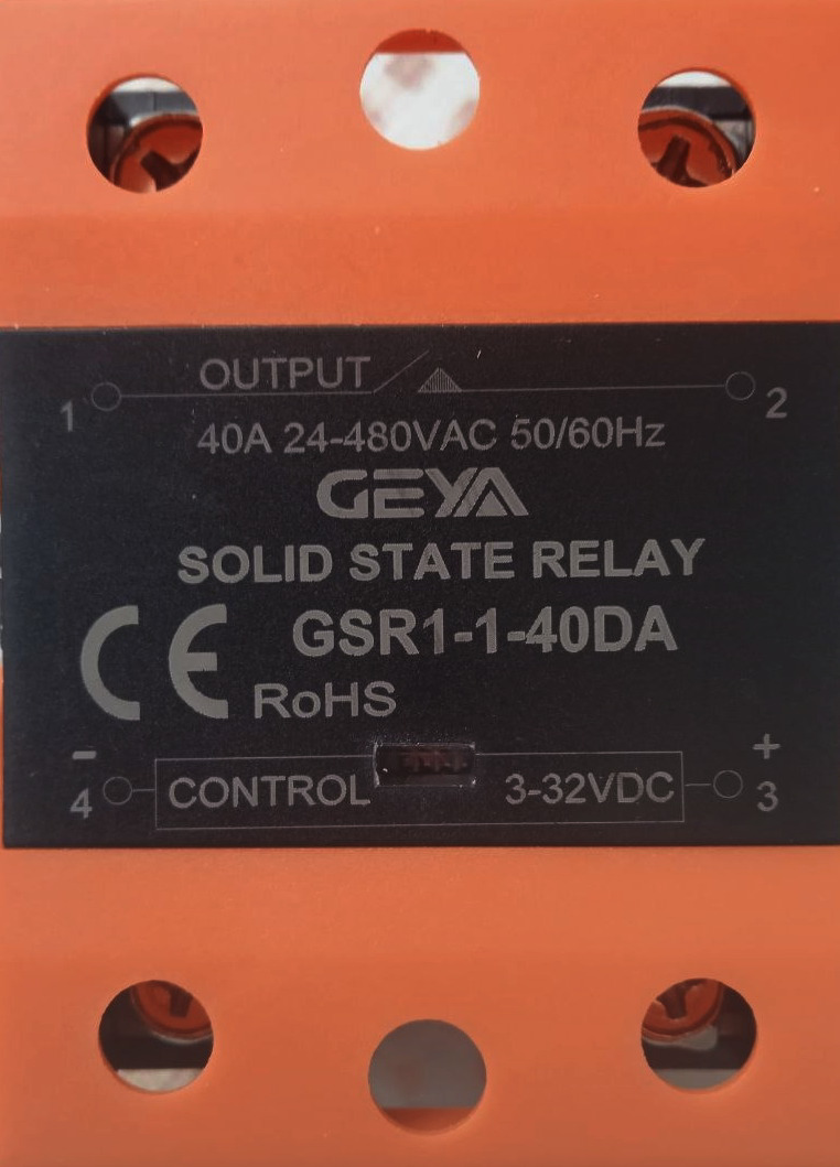
The Geya GSR1-1-40DA is a solid-state relay (SSR) designed for high-performance switching applications. Unlike traditional electromechanical relays, this SSR operates without moving parts, ensuring minimal heat generation, no mechanical wear, and reliable, fast switching. It is ideal for applications requiring high current handling and long operational life.
Explore Projects Built with SSR GSR1-1-40DA
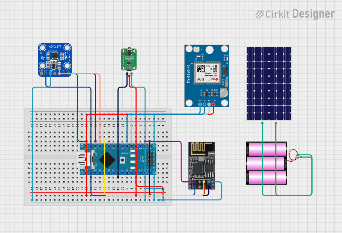


Explore Projects Built with SSR GSR1-1-40DA
Common Applications and Use Cases
- Industrial automation systems
- Heating, ventilation, and air conditioning (HVAC) systems
- Motor control and protection
- Lighting control systems
- Temperature control in ovens and furnaces
- Home appliances and smart home systems
Technical Specifications
The following table outlines the key technical details of the GSR1-1-40DA:
| Parameter | Specification |
|---|---|
| Manufacturer | Geya |
| Model Number | GSR1-1-40DA |
| Input Control Voltage | 3-32 VDC |
| Output Load Voltage | 24-380 VAC |
| Maximum Load Current | 40 A |
| Control Current | ≤ 10 mA |
| On-State Voltage Drop | ≤ 1.5 V |
| Off-State Leakage Current | ≤ 2 mA |
| Isolation Voltage | ≥ 2500 VAC |
| Operating Temperature | -30°C to +80°C |
| Mounting Type | Panel-mounted |
| Dimensions | 58 mm x 45 mm x 30 mm |
Pin Configuration and Descriptions
The GSR1-1-40DA has four terminals, as described in the table below:
| Pin Number | Label | Description |
|---|---|---|
| 1 | + | Positive terminal for DC control input |
| 2 | - | Negative terminal for DC control input |
| 3 | Load (L1) | AC load input terminal |
| 4 | Load (L2) | AC load output terminal |
Usage Instructions
How to Use the GSR1-1-40DA in a Circuit
Input Control Connection:
- Connect the DC control signal (3-32 VDC) to the
+and-terminals of the SSR. - Ensure the control voltage is within the specified range to avoid damage.
- Connect the DC control signal (3-32 VDC) to the
Load Connection:
- Connect the AC load to the
Load (L1)andLoad (L2)terminals. - Ensure the load voltage and current do not exceed the SSR's maximum ratings (24-380 VAC, 40 A).
- Connect the AC load to the
Mounting:
- Securely mount the SSR on a heat sink or panel to ensure proper heat dissipation.
- Use thermal paste if necessary to improve heat transfer.
Power Supply:
- Verify that the power supply for the control circuit and the load circuit are properly isolated.
Important Considerations and Best Practices
- Heat Dissipation: Solid-state relays generate heat during operation. Use a heat sink or cooling fan to maintain optimal operating temperatures.
- Surge Protection: Install a snubber circuit or varistor across the load terminals to protect the SSR from voltage spikes.
- Load Type: Ensure the SSR is suitable for the type of load (e.g., resistive, inductive, or capacitive).
- Wiring: Use appropriately rated wires and connectors to handle the load current safely.
- Testing: Before connecting the SSR to the final application, test it with a low-power load to verify proper operation.
Example: Connecting to an Arduino UNO
The GSR1-1-40DA can be controlled using an Arduino UNO. Below is an example circuit and code to toggle an AC load using the SSR.
Circuit Diagram
- Connect the Arduino's digital output pin (e.g., pin 9) to the
+terminal of the SSR. - Connect the
-terminal of the SSR to the Arduino's GND. - Connect the AC load to the
Load (L1)andLoad (L2)terminals of the SSR. - Ensure the AC load is powered by an appropriate AC voltage source.
Arduino Code
// Define the pin connected to the SSR control input
const int ssrPin = 9;

void setup() {
  // Set the SSR pin as an output
  pinMode(ssrPin, OUTPUT);
}

void loop() {
  // Turn the SSR (and connected load) ON
  digitalWrite(ssrPin, HIGH);
  delay(5000); // Keep the load ON for 5 seconds

  // Turn the SSR (and connected load) OFF
  digitalWrite(ssrPin, LOW);
  delay(5000); // Keep the load OFF for 5 seconds
}
Notes:
- Ensure the Arduino's output voltage (5 V) is compatible with the SSR's control input range (3-32 VDC).
- Use an external power supply if the Arduino cannot provide sufficient current for the SSR control input.
Troubleshooting and FAQs
Common Issues and Solutions
| Issue | Possible Cause | Solution |
|---|---|---|
| SSR does not turn ON | Insufficient control voltage or current | Verify the control voltage is within 3-32 VDC |
| SSR does not turn OFF | Leakage current in the load circuit | Use a load with higher resistance or add a bleeder resistor |
| Excessive heat generation | Inadequate heat dissipation | Install a heat sink or cooling fan |
| Load does not operate correctly | Incorrect wiring or load type mismatch | Double-check wiring and ensure load compatibility |
| Flickering or unstable operation | Electrical noise or interference | Add a capacitor or snubber circuit to suppress noise |
FAQs
Can the GSR1-1-40DA handle inductive loads?
- Yes, but it is recommended to use a snubber circuit to protect the SSR from voltage spikes caused by inductive loads.
What happens if the control voltage exceeds 32 VDC?
- Exceeding the maximum control voltage can damage the SSR. Always ensure the control voltage stays within the specified range.
Do I need a heat sink for low-current applications?
- For low-current loads, a heat sink may not be necessary. However, for loads approaching the maximum current rating (40 A), a heat sink is essential.
Can I use the SSR with a DC load?
- No, the GSR1-1-40DA is designed for AC loads only. For DC loads, use a DC-specific SSR.
By following this documentation, users can effectively integrate the Geya GSR1-1-40DA into their projects for reliable and efficient switching performance.