
How to Use ESP32-S3-DevKit-C: Examples, Pinouts, and Specs
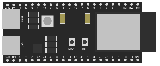
 Design with ESP32-S3-DevKit-C in Cirkit Designer
Introduction
The ESP32-S3-DevKit-C is a development board manufactured by Espressif, featuring the powerful ESP32-S3 chip. This board is designed for IoT applications and prototyping, offering integrated Wi-Fi and Bluetooth Low Energy (BLE) capabilities. It is equipped with a variety of peripherals and interfaces, making it suitable for a wide range of projects, from smart home devices to industrial automation.
Explore Projects Built with ESP32-S3-DevKit-C
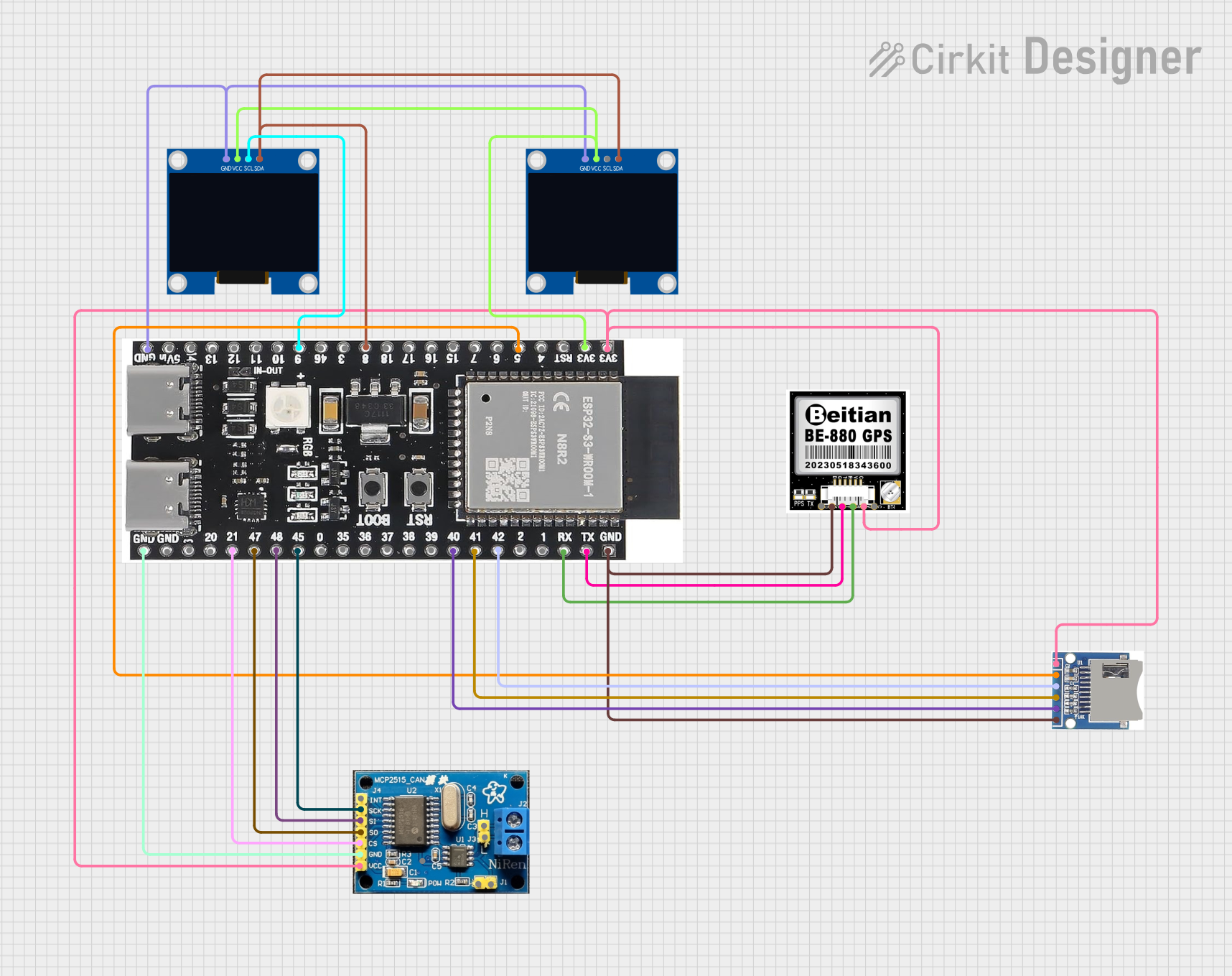 Open Project in Cirkit Designer
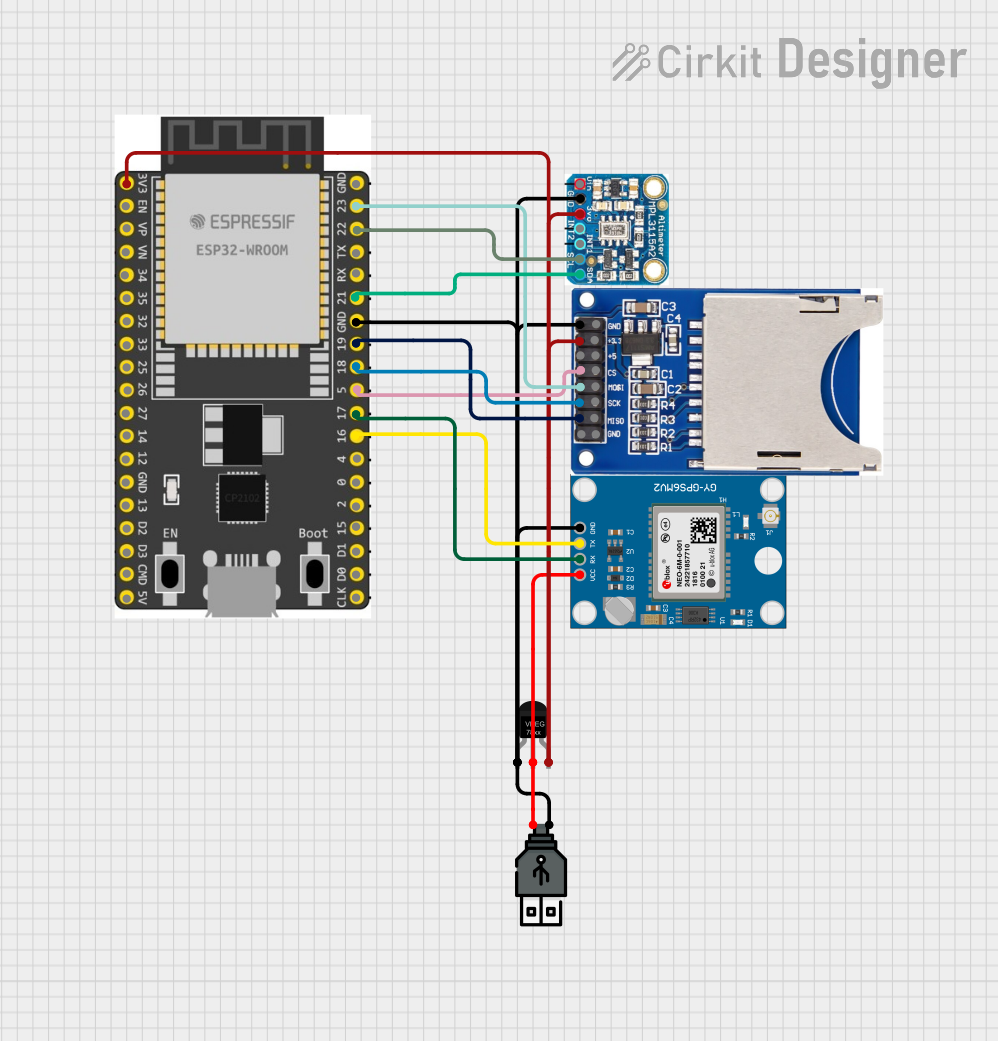 Open Project in Cirkit Designer
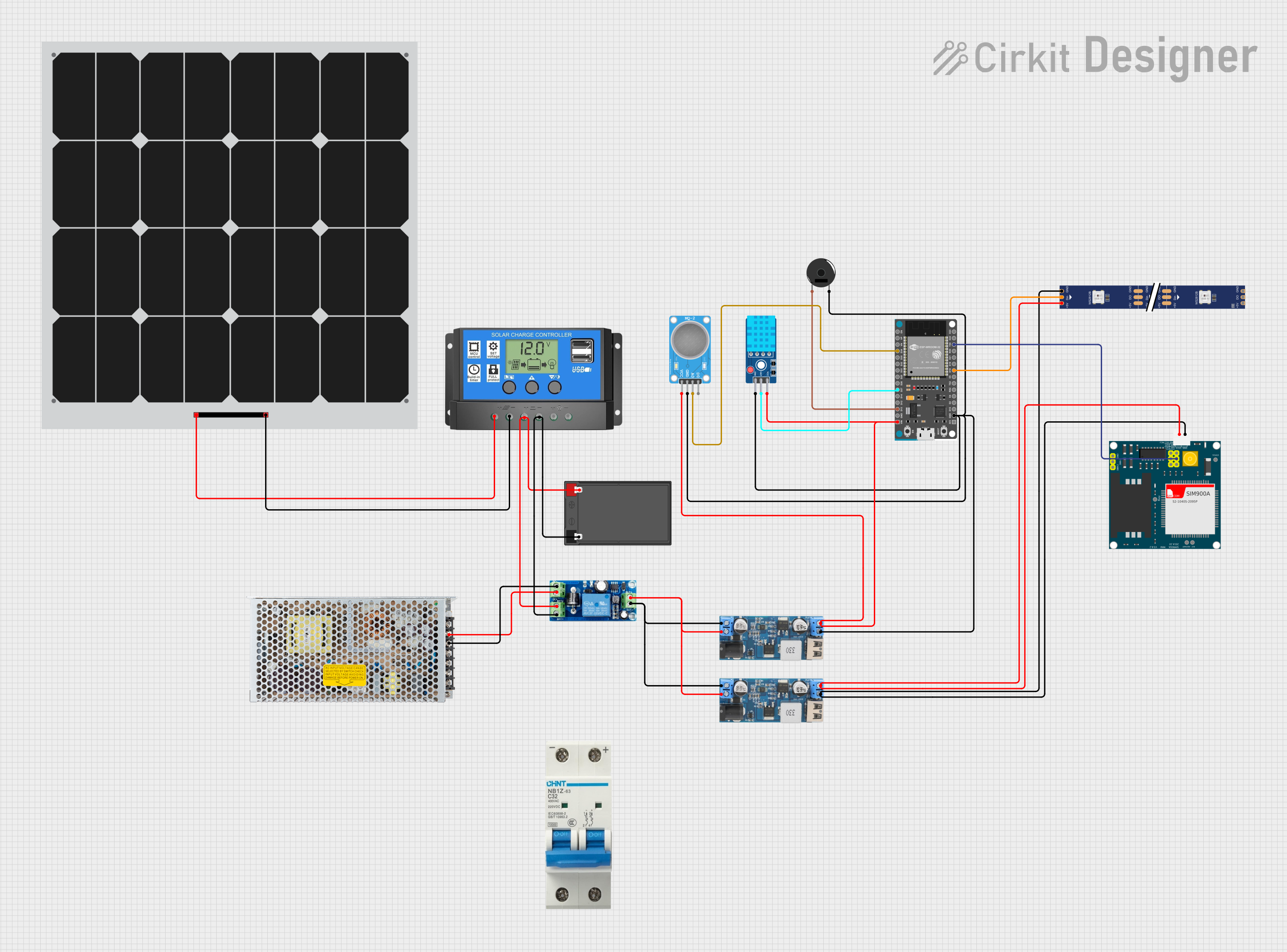 Open Project in Cirkit Designer
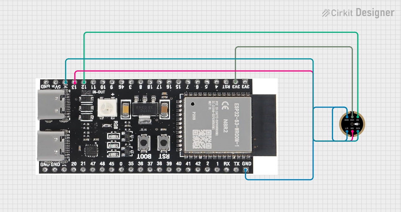 Open Project in Cirkit Designer
Explore Projects Built with ESP32-S3-DevKit-C
Open Project in Cirkit DesignerOpen Project in Cirkit DesignerOpen Project in Cirkit DesignerOpen Project in Cirkit DesignerCommon Applications
- IoT devices and smart home automation
- Wearable electronics
- Wireless sensor networks
- Industrial control systems
- Prototyping for AI and machine learning applications
Technical Specifications
Key Technical Details
| Specification | Value |
|---|---|
| Microcontroller | ESP32-S3 (Xtensa® 32-bit LX7 dual-core CPU) |
| Wireless Connectivity | Wi-Fi 802.11 b/g/n, Bluetooth 5 (LE) |
| Flash Memory | 4 MB (varies by model) |
| PSRAM | 8 MB (optional, varies by model) |
| Operating Voltage | 3.3V |
| Input Voltage Range | 5V (via USB) |
| GPIO Pins | 21 (configurable for various functions) |
| Interfaces | SPI, I2C, I2S, UART, PWM, ADC, DAC |
| ADC Resolution | 12-bit |
| USB Interface | USB Type-C (native USB support) |
| Dimensions | 54 mm x 25.5 mm |
Pin Configuration and Descriptions
The ESP32-S3-DevKit-C features a 2-row pin header layout. Below is the pin configuration:
| Pin Number | Pin Name | Description |
|---|---|---|
| 1 | 3V3 | 3.3V power output |
| 2 | GND | Ground |
| 3 | IO0 | GPIO0, used for boot mode selection |
| 4 | IO1 | GPIO1, general-purpose I/O |
| 5 | IO2 | GPIO2, general-purpose I/O |
| 6 | IO3 | GPIO3, general-purpose I/O |
| 7 | IO4 | GPIO4, general-purpose I/O |
| 8 | IO5 | GPIO5, general-purpose I/O |
| 9 | IO6 | GPIO6, general-purpose I/O |
| 10 | IO7 | GPIO7, general-purpose I/O |
| ... | ... | ... (additional GPIO pins available) |
| 21 | EN | Enable pin, used to reset the chip |
Note: Refer to the official Espressif datasheet for the complete pinout and advanced configurations.
Usage Instructions
How to Use the ESP32-S3-DevKit-C in a Circuit
Powering the Board:
- Connect the board to your computer or power source using a USB Type-C cable. The board operates at 3.3V internally but accepts 5V input via USB.
Programming the Board:
- Install the Arduino IDE or Espressif's ESP-IDF (Espressif IoT Development Framework).
- Add the ESP32-S3 board support package to your development environment.
- Write your code and upload it to the board via the USB interface.
Connecting Peripherals:
- Use the GPIO pins to connect sensors, actuators, or other peripherals.
- Configure the pins in your code for the desired functionality (e.g., input, output, PWM).
Wi-Fi and Bluetooth Setup:
- Use the built-in Wi-Fi and BLE libraries to connect to networks or pair with devices.
Important Considerations and Best Practices
- Voltage Levels: Ensure all connected peripherals operate at 3.3V logic levels to avoid damaging the board.
- Boot Mode: To enter bootloader mode, hold the BOOT button while pressing the EN (reset) button.
- Power Supply: If powering the board externally, ensure the voltage is regulated to 5V.
- Heat Management: The ESP32-S3 chip may heat up during operation. Ensure proper ventilation if used in enclosed spaces.
Example Code for Arduino IDE
Below is an example of how to blink an LED connected to GPIO2:
// Define the GPIO pin for the LED
#define LED_PIN 2

void setup() {
  // Set the LED pin as an output
  pinMode(LED_PIN, OUTPUT);
}

void loop() {
  // Turn the LED on
  digitalWrite(LED_PIN, HIGH);
  delay(1000); // Wait for 1 second

  // Turn the LED off
  digitalWrite(LED_PIN, LOW);
  delay(1000); // Wait for 1 second
}
Example Code for Wi-Fi Connection
Below is an example of connecting the ESP32-S3 to a Wi-Fi network:
#include <WiFi.h>

// Replace with your network credentials
const char* ssid = "Your_SSID";
const char* password = "Your_PASSWORD";

void setup() {
  Serial.begin(115200); // Initialize serial communication
  WiFi.begin(ssid, password); // Start Wi-Fi connection

  // Wait for the connection to establish
  while (WiFi.status() != WL_CONNECTED) {
    delay(1000);
    Serial.println("Connecting to Wi-Fi...");
  }

  Serial.println("Connected to Wi-Fi!");
  Serial.print("IP Address: ");
  Serial.println(WiFi.localIP());
}

void loop() {
  // Add your main code here
}
Troubleshooting and FAQs
Common Issues and Solutions
Board Not Detected by Computer:
- Ensure the USB cable is functional and supports data transfer.
- Install the necessary USB drivers for the ESP32-S3.
Code Upload Fails:
- Check that the correct board and port are selected in the IDE.
- Hold the BOOT button while uploading the code to enter bootloader mode.
Wi-Fi Connection Fails:
- Verify the SSID and password are correct.
- Ensure the Wi-Fi network is within range and supports 2.4 GHz (ESP32-S3 does not support 5 GHz).
Peripherals Not Working:
- Double-check the wiring and ensure the GPIO pins are configured correctly in the code.
- Confirm that the peripherals are compatible with 3.3V logic levels.
FAQs
Q: Can I power the ESP32-S3-DevKit-C with a battery?
A: Yes, you can power the board using a 3.7V LiPo battery connected to the appropriate pins, but ensure proper voltage regulation.
Q: Does the ESP32-S3 support over-the-air (OTA) updates?
A: Yes, the ESP32-S3 supports OTA updates, allowing you to update firmware wirelessly.
Q: Can I use the ESP32-S3-DevKit-C for AI applications?
A: Yes, the ESP32-S3 includes hardware acceleration for AI tasks, making it suitable for lightweight AI and machine learning applications.
Q: What is the maximum Wi-Fi range of the ESP32-S3?
A: The range depends on environmental factors but typically extends up to 100 meters in open spaces.
For additional support, refer to the official Espressif documentation or community forums.