Cirkit Designer Logo
Cirkit Designer
Your all-in-one circuit design IDE
Home / 
Component Documentation

How to Use MCP23017: Examples, Pinouts, and Specs

Image of MCP23017
Cirkit Designer LogoDesign with MCP23017 in Cirkit Designer

Introduction

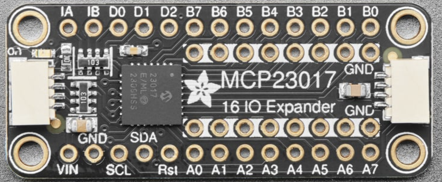
The MCP23017 is a 16-bit I/O expander with serial interface provided by Microchip Technology Inc. It offers an easy way to add additional general-purpose input/output (GPIO) pins to a microcontroller via the I2C bus. This component is particularly useful in applications where additional I/Os are needed, such as in button matrices, LED control, or when interfacing with multiple sensors that do not have a digital interface.

Common applications include:

  • Expanding the number of I/Os in microcontroller-based projects
  • Home automation systems
  • Industrial control systems
  • Prototyping and hobbyist projects

Explore Projects Built with MCP23017

Use Cirkit Designer to design, explore, and prototype these projects online. Some projects support real-time simulation. Click "Open Project" to start designing instantly!
MCP23017-Expanded I/O Interface with ADS1115 ADC and ESP32 Control
Image of door and window sensors: A project utilizing MCP23017 in a practical application
This circuit features two MCP23017 I/O expanders interfaced with multiple switches, allowing for the expansion of input capabilities. The MCP23017s are connected via I2C to an Olimex ESP32-EVB microcontroller, which likely manages the input states from the switches. Additionally, an Adafruit ADS1115 16-bit ADC is included, suggesting that some analog inputs are being monitored, with the ADC also interfaced with the ESP32 via I2C.
Cirkit Designer LogoOpen Project in Cirkit Designer
I2C-Controlled Relay Switching with ESP32 and MCP23017 for Home Automation
Image of Vloerverwarming: A project utilizing MCP23017 in a practical application
This circuit appears to be a control system utilizing two MCP23017 I/O expanders interfaced with an Olimex ESP32-EVB microcontroller via I2C communication, as indicated by the SDA and SCL connections with pull-up resistors. The MCP23017 expanders control an 8-channel relay module, allowing the microcontroller to switch various loads, potentially for home automation or industrial control. Additionally, there is an Adafruit ADS1115 16-bit ADC for analog signal measurement, and several heating actuators and a thermostat are connected, suggesting temperature control functionality.
Cirkit Designer LogoOpen Project in Cirkit Designer
ESP32-Based I2C Communication Hub with Multiplexer and Expander
Image of Lights: A project utilizing MCP23017 in a practical application
This circuit features an Olimex ESP32-EVB microcontroller unit (MCU) for processing and connectivity, interfaced with an MCP23017 I/O expander and an Adafruit TCA9548A I2C multiplexer to expand the number of I/O lines and allow multiple I2C devices to communicate with the MCU over the same bus. Pull-up resistors are connected to the I2C lines for proper bus operation, and both the MCP23017 and TCA9548A have their reset lines pulled high, likely for normal operation without external reset control.
Cirkit Designer LogoOpen Project in Cirkit Designer
ESP32-Based Vibration Motor Controller with I2C IO Expansion
Image of VIBRATYION: A project utilizing MCP23017 in a practical application
This circuit features an ESP32 Wroom Dev Kit microcontroller interfaced with an MCP23017 I/O expansion board via I2C communication, utilizing GPIO 21 and GPIO 22 for SDA and SCL lines, respectively. A vibration motor is controlled by an NPN transistor acting as a switch, with a diode for back EMF protection and a resistor to limit base current. The ESP32 can control the motor by sending signals to the MCP23017, which then interfaces with the transistor to turn the motor on or off.
Cirkit Designer LogoOpen Project in Cirkit Designer

Explore Projects Built with MCP23017

Use Cirkit Designer to design, explore, and prototype these projects online. Some projects support real-time simulation. Click "Open Project" to start designing instantly!
Image of door and window sensors: A project utilizing MCP23017 in a practical application
MCP23017-Expanded I/O Interface with ADS1115 ADC and ESP32 Control
This circuit features two MCP23017 I/O expanders interfaced with multiple switches, allowing for the expansion of input capabilities. The MCP23017s are connected via I2C to an Olimex ESP32-EVB microcontroller, which likely manages the input states from the switches. Additionally, an Adafruit ADS1115 16-bit ADC is included, suggesting that some analog inputs are being monitored, with the ADC also interfaced with the ESP32 via I2C.
Cirkit Designer LogoOpen Project in Cirkit Designer
Image of Vloerverwarming: A project utilizing MCP23017 in a practical application
I2C-Controlled Relay Switching with ESP32 and MCP23017 for Home Automation
This circuit appears to be a control system utilizing two MCP23017 I/O expanders interfaced with an Olimex ESP32-EVB microcontroller via I2C communication, as indicated by the SDA and SCL connections with pull-up resistors. The MCP23017 expanders control an 8-channel relay module, allowing the microcontroller to switch various loads, potentially for home automation or industrial control. Additionally, there is an Adafruit ADS1115 16-bit ADC for analog signal measurement, and several heating actuators and a thermostat are connected, suggesting temperature control functionality.
Cirkit Designer LogoOpen Project in Cirkit Designer
Image of Lights: A project utilizing MCP23017 in a practical application
ESP32-Based I2C Communication Hub with Multiplexer and Expander
This circuit features an Olimex ESP32-EVB microcontroller unit (MCU) for processing and connectivity, interfaced with an MCP23017 I/O expander and an Adafruit TCA9548A I2C multiplexer to expand the number of I/O lines and allow multiple I2C devices to communicate with the MCU over the same bus. Pull-up resistors are connected to the I2C lines for proper bus operation, and both the MCP23017 and TCA9548A have their reset lines pulled high, likely for normal operation without external reset control.
Cirkit Designer LogoOpen Project in Cirkit Designer
Image of VIBRATYION: A project utilizing MCP23017 in a practical application
ESP32-Based Vibration Motor Controller with I2C IO Expansion
This circuit features an ESP32 Wroom Dev Kit microcontroller interfaced with an MCP23017 I/O expansion board via I2C communication, utilizing GPIO 21 and GPIO 22 for SDA and SCL lines, respectively. A vibration motor is controlled by an NPN transistor acting as a switch, with a diode for back EMF protection and a resistor to limit base current. The ESP32 can control the motor by sending signals to the MCP23017, which then interfaces with the transistor to turn the motor on or off.
Cirkit Designer LogoOpen Project in Cirkit Designer

Technical Specifications

Key Technical Details

  • Operating Voltage: 1.8V to 5.5V
  • I2C Interface
  • 16 GPIO pins, configurable as input or output
  • Interrupt output pins
  • High-speed I2C interface (100 kHz, 400 kHz, 1.7 MHz)
  • Three hardware address pins to allow up to eight devices on the bus

Pin Configuration and Descriptions

Pin Number Pin Name Description
1-2 A0-A1 Hardware address pins to configure the I2C address
3 A2 Hardware address pin to configure the I2C address
4 VSS Ground (0V)
5 SCL Serial Clock Line for I2C
6 SDA Serial Data Line for I2C
7 RESET Active-low reset input
8-9 INTA-INTB Interrupt output pins
10-17 GPA0-GPA7 GPIO Port A pins
18-25 GPB0-GPB7 GPIO Port B pins
26 VDD Positive power supply

Usage Instructions

Interfacing with a Microcontroller

  1. Connect VDD to the microcontroller's power supply (3.3V or 5V depending on the logic level).
  2. Connect VSS to the ground of the microcontroller.
  3. Connect SDA and SCL to the corresponding I2C pins on the microcontroller.
  4. Set the A0, A1, and A2 pins to the desired logic levels to set the I2C address.
  5. Connect the RESET pin to a digital output on the microcontroller if hardware reset functionality is required.

Programming the MCP23017

To use the MCP23017 with an Arduino UNO, you can use the Adafruit MCP23017 Arduino library. Here is a simple example to initialize the MCP23017 and set all pins to output:

#include <Wire.h>
#include <Adafruit_MCP23017.h>

// Create an MCP23017 object
Adafruit_MCP23017 mcp;

void setup() {
  Wire.begin();        // Initialize I2C bus
  mcp.begin();         // Initialize MCP23017 with default address 0x20

  // Set all pins to output
  for (int i = 0; i < 16; i++) {
    mcp.pinMode(i, OUTPUT);
  }
}

void loop() {
  // Your code here to control the GPIO pins
}

Important Considerations and Best Practices

  • Ensure that the power supply voltage matches the logic level of the microcontroller to avoid damage.
  • Use pull-up resistors on the SDA and SCL lines if they are not provided on the microcontroller board.
  • Avoid setting the same I2C address on multiple devices on the same bus.
  • Use the interrupt pins to efficiently detect input changes without polling.

Troubleshooting and FAQs

Common Issues

  • I2C Communication Failure: Check the wiring of SDA and SCL, ensure pull-up resistors are in place, and verify that there are no address conflicts on the I2C bus.
  • Unexpected Resets: Ensure that the RESET pin is not floating and is connected properly if used.
  • GPIO Pin Not Responding: Verify that the pin has been configured correctly as input or output.

Solutions and Tips for Troubleshooting

  • Use I2C scanner code to confirm that the MCP23017 is detected on the I2C bus.
  • Check the power supply and ground connections.
  • Use a logic analyzer or oscilloscope to debug the I2C signal if necessary.

FAQs

Q: Can I use multiple MCP23017 devices on the same I2C bus? A: Yes, you can use up to 8 MCP23017 devices on the same I2C bus by configuring the A0, A1, and A2 pins to different addresses.

Q: What is the maximum I2C speed that MCP23017 supports? A: The MCP23017 supports I2C speeds up to 1.7 MHz.

Q: How do I use the interrupt feature of the MCP23017? A: Configure the interrupt control registers to define the interrupt condition for each pin, and connect the INTA or INTB pin to an interrupt-capable pin on your microcontroller.

This documentation provides a comprehensive guide to using the MCP23017 I/O expander. For more detailed information, refer to the MCP23017 datasheet provided by Microchip Technology Inc.