How to Use relaymk: Examples, Pinouts, and Specs
Introduction
The RelayMK by NJ (Manufacturer Part ID: REL) is a relay module designed to act as an electronic switch. It uses an electromagnet to mechanically operate a switch, enabling the control of high-voltage or high-current devices using low-voltage signals. This makes it an essential component for interfacing microcontrollers, such as Arduino, with devices like motors, lights, and home appliances.
Explore Projects Built with relaymk
![Image of [Circuit Design] RFID-Based Equipment Logger for DPWH : A project utilizing relaymk in a practical application](https://abacasstorageaccnt.blob.core.windows.net/cirkit/c81f4194-7010-43d8-91fe-f2eb970df771.png)
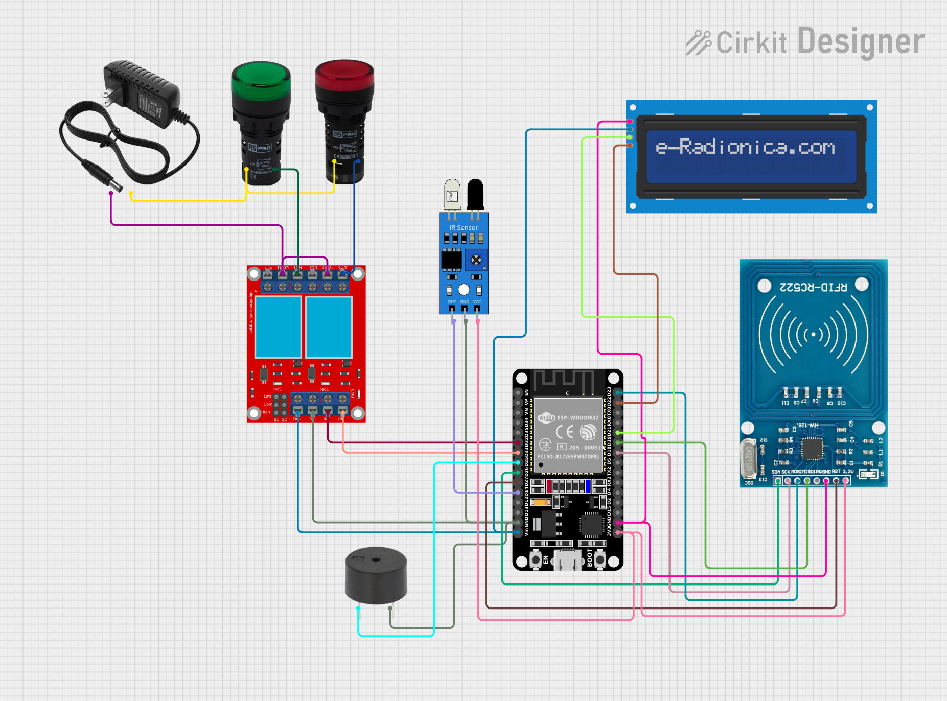
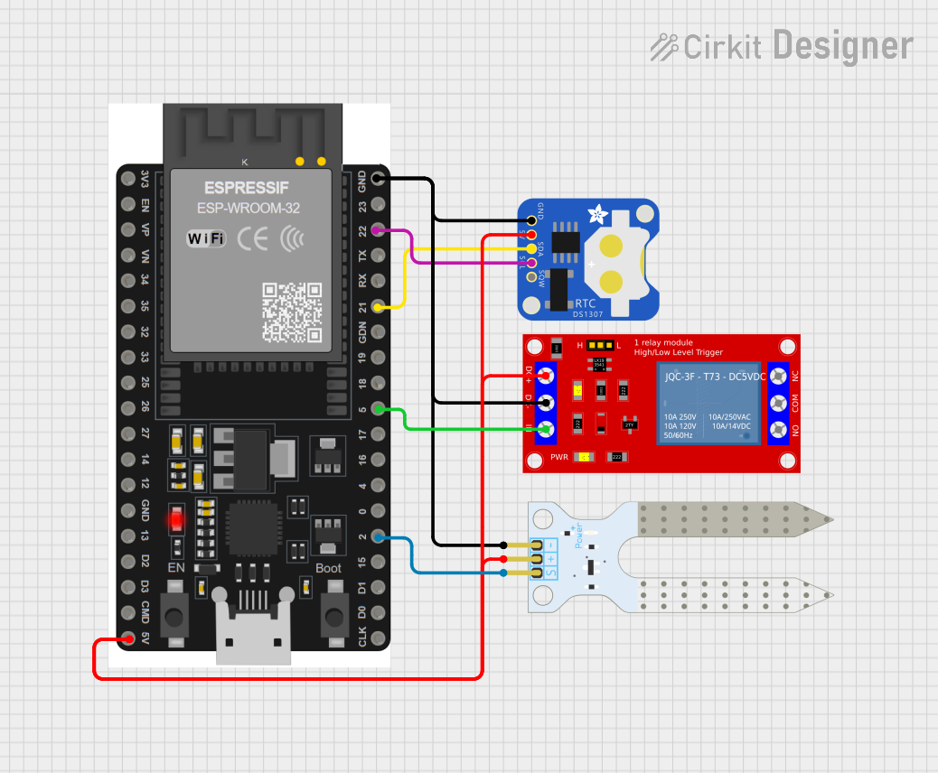
Explore Projects Built with relaymk
Common Applications and Use Cases
- Home automation systems (e.g., controlling lights or fans)
- Industrial control systems
- Motor control circuits
- IoT projects requiring high-power device control
- Safety circuits for isolating high-voltage systems from low-voltage control systems
Technical Specifications
The following table outlines the key technical details of the RelayMK module:
| Parameter | Value |
|---|---|
| Operating Voltage | 5V DC |
| Trigger Voltage | 3.3V to 5V DC |
| Maximum Load Voltage | 250V AC / 30V DC |
| Maximum Load Current | 10A |
| Relay Type | SPDT (Single Pole Double Throw) |
| Isolation | Optocoupler-based isolation |
| Dimensions | 50mm x 26mm x 18mm |
| Weight | 15g |
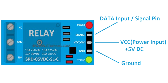
Pin Configuration and Descriptions
The RelayMK module has the following pin configuration:
Input Pins
| Pin Name | Description |
|---|---|
| VCC | Connect to 5V DC power supply |
| GND | Connect to ground |
| IN | Control signal input (3.3V or 5V logic) |
Output Terminals
| Terminal Name | Description |
|---|---|
| NO (Normally Open) | Connect to the load; remains open until relay is activated |
| COM (Common) | Common terminal for the load |
| NC (Normally Closed) | Connect to the load; remains closed until relay is activated |
Usage Instructions
How to Use the RelayMK in a Circuit
- Power the Module: Connect the VCC pin to a 5V DC power source and the GND pin to ground.
- Control Signal: Connect the IN pin to a digital output pin of a microcontroller (e.g., Arduino UNO). The relay will activate when the control signal is HIGH.
- Load Connection:
- Connect the device you want to control (e.g., a light bulb or motor) to the NO or NC terminal, depending on your desired behavior.
- Connect the other end of the device to the COM terminal.
- Isolation: Ensure proper isolation between the low-voltage control circuit and the high-voltage load to prevent damage or hazards.
Important Considerations and Best Practices
- Power Supply: Ensure the module is powered with a stable 5V DC supply.
- Load Ratings: Do not exceed the maximum load voltage (250V AC / 30V DC) or current (10A).
- Flyback Diode: If controlling an inductive load (e.g., a motor), use a flyback diode across the load to protect the relay from voltage spikes.
- Safety: Always handle high-voltage connections with care. Disconnect power before making any changes to the circuit.
- Logic Level Compatibility: The IN pin is compatible with both 3.3V and 5V logic levels, making it suitable for most microcontrollers.
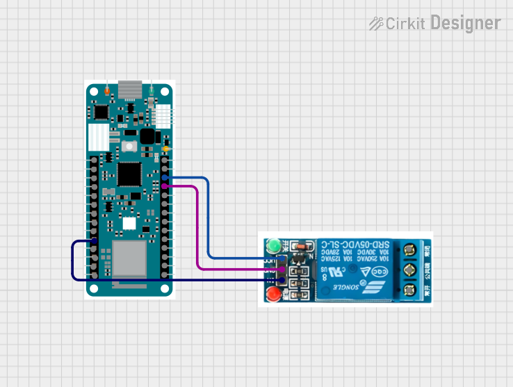
Example: Connecting RelayMK to an Arduino UNO
Below is an example of how to control a light bulb using the RelayMK module and an Arduino UNO:
Circuit Diagram
- Connect the RelayMK's VCC to the Arduino's 5V pin.
- Connect the RelayMK's GND to the Arduino's GND pin.
- Connect the RelayMK's IN pin to Arduino digital pin 7.
- Connect the light bulb to the NO and COM terminals of the relay.
Arduino Code
// Define the pin connected to the relay module
const int relayPin = 7;

void setup() {
  // Set the relay pin as an output
  pinMode(relayPin, OUTPUT);

  // Ensure the relay is off initially
  digitalWrite(relayPin, LOW);
}

void loop() {
  // Turn the relay on (light bulb ON)
  digitalWrite(relayPin, HIGH);
  delay(5000); // Keep the light ON for 5 seconds

  // Turn the relay off (light bulb OFF)
  digitalWrite(relayPin, LOW);
  delay(5000); // Keep the light OFF for 5 seconds
}
Troubleshooting and FAQs
Common Issues and Solutions
Relay Not Activating
- Cause: Insufficient control signal voltage.
- Solution: Ensure the IN pin receives a HIGH signal (3.3V or 5V) from the microcontroller.
Load Not Turning On/Off
- Cause: Incorrect wiring of the load to the relay terminals.
- Solution: Verify the load is connected to the correct terminals (NO/NC and COM).
Relay Clicking but No Output
- Cause: Faulty relay or excessive load current.
- Solution: Check the load's current and voltage ratings. Replace the relay if necessary.
Microcontroller Resetting
- Cause: Voltage spikes from the relay coil.
- Solution: Add a flyback diode across the relay coil to suppress voltage spikes.
FAQs
Q1: Can I use the RelayMK with a 3.3V microcontroller like the ESP32?
A1: Yes, the IN pin is compatible with 3.3V logic levels. Ensure the module is powered with 5V.
Q2: Can I control multiple relays with one microcontroller?
A2: Yes, as long as each relay is connected to a separate digital output pin and the microcontroller can supply sufficient current.
Q3: Is the RelayMK suitable for switching DC motors?
A3: Yes, but ensure the motor's voltage and current do not exceed the relay's maximum ratings. Use a flyback diode for protection.
Q4: Can I use the RelayMK to control both AC and DC loads?
A4: Yes, the RelayMK supports both AC (up to 250V) and DC (up to 30V) loads. Always adhere to the specified ratings.