Cirkit Designer Logo
Cirkit Designer
Your all-in-one circuit design IDE
Home / 
Component Documentation

How to Use 3-24V Buzzer: Examples, Pinouts, and Specs

Image of 3-24V Buzzer
Cirkit Designer LogoDesign with 3-24V Buzzer in Cirkit Designer

Introduction

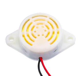
The 3-24V Buzzer is a sound-emitting electronic component designed to operate within a wide voltage range of 3 to 24 volts. It is commonly used in circuits to provide audio feedback, alarms, notifications, and alerts. This versatile component is ideal for applications in security systems, timers, and user interfaces where audible signals are required.

Explore Projects Built with 3-24V Buzzer

Use Cirkit Designer to design, explore, and prototype these projects online. Some projects support real-time simulation. Click "Open Project" to start designing instantly!
Battery-Powered Buzzer Circuit
Image of  Buzzer with AA battery: A project utilizing 3-24V Buzzer in a practical application
This circuit consists of a simple buzzer connected to a 3V battery source. The positive terminal of the battery is connected to the buzzer's power input, and the negative terminal is connected to the buzzer's ground. The circuit is designed to power the buzzer continuously, producing a constant sound or tone as long as the battery provides sufficient voltage.
Cirkit Designer LogoOpen Project in Cirkit Designer
Battery-Powered LED and Buzzer Control Circuit Using BC547 Transistors
Image of Water level Indicator : A project utilizing 3-24V Buzzer in a practical application
This circuit is a multi-indicator system powered by a 9V battery, utilizing three BC547 transistors to control three LEDs (red, green, and yellow) and a buzzer. Each transistor is configured to switch its respective LED and the buzzer on and off, likely based on external signals connected via alligator clips.
Cirkit Designer LogoOpen Project in Cirkit Designer
Battery-Powered PIR Motion Sensor Alarm with Relay and Buzzer
Image of motion detector using pir motio0n sensor: A project utilizing 3-24V Buzzer in a practical application
This circuit is a motion-activated alarm system. It uses a PIR motion sensor to detect movement, which triggers a relay module to activate a buzzer powered by a 9V battery, providing an audible alert.
Cirkit Designer LogoOpen Project in Cirkit Designer
Battery-Powered IR Sensor with Buzzer Alert System
Image of fire detector: A project utilizing 3-24V Buzzer in a practical application
This circuit is a sensor-activated buzzer system powered by a battery. An IR sensor detects an object and triggers an NPN transistor, which in turn activates a relay to power a buzzer. The circuit includes a voltage regulator to ensure stable 5V power supply and a rocker switch for manual control.
Cirkit Designer LogoOpen Project in Cirkit Designer

Explore Projects Built with 3-24V Buzzer

Use Cirkit Designer to design, explore, and prototype these projects online. Some projects support real-time simulation. Click "Open Project" to start designing instantly!
Image of  Buzzer with AA battery: A project utilizing 3-24V Buzzer in a practical application
Battery-Powered Buzzer Circuit
This circuit consists of a simple buzzer connected to a 3V battery source. The positive terminal of the battery is connected to the buzzer's power input, and the negative terminal is connected to the buzzer's ground. The circuit is designed to power the buzzer continuously, producing a constant sound or tone as long as the battery provides sufficient voltage.
Cirkit Designer LogoOpen Project in Cirkit Designer
Image of Water level Indicator : A project utilizing 3-24V Buzzer in a practical application
Battery-Powered LED and Buzzer Control Circuit Using BC547 Transistors
This circuit is a multi-indicator system powered by a 9V battery, utilizing three BC547 transistors to control three LEDs (red, green, and yellow) and a buzzer. Each transistor is configured to switch its respective LED and the buzzer on and off, likely based on external signals connected via alligator clips.
Cirkit Designer LogoOpen Project in Cirkit Designer
Image of motion detector using pir motio0n sensor: A project utilizing 3-24V Buzzer in a practical application
Battery-Powered PIR Motion Sensor Alarm with Relay and Buzzer
This circuit is a motion-activated alarm system. It uses a PIR motion sensor to detect movement, which triggers a relay module to activate a buzzer powered by a 9V battery, providing an audible alert.
Cirkit Designer LogoOpen Project in Cirkit Designer
Image of fire detector: A project utilizing 3-24V Buzzer in a practical application
Battery-Powered IR Sensor with Buzzer Alert System
This circuit is a sensor-activated buzzer system powered by a battery. An IR sensor detects an object and triggers an NPN transistor, which in turn activates a relay to power a buzzer. The circuit includes a voltage regulator to ensure stable 5V power supply and a rocker switch for manual control.
Cirkit Designer LogoOpen Project in Cirkit Designer

Technical Specifications

  • Operating Voltage: 3V to 24V DC
  • Current Consumption: Typically 5-30 mA (varies with voltage)
  • Sound Output: ~85 dB at 12V (varies with voltage and distance)
  • Frequency: ~2 kHz (typical for piezoelectric buzzers)
  • Polarity: Positive and negative terminals for DC operation
  • Type: Active buzzer (produces sound when powered, no external signal required)
  • Dimensions: Varies by model, typically cylindrical with a diameter of 12-15 mm

Pin Configuration and Descriptions

Pin Name Description
Positive (+) Connect to the positive terminal of the power supply (3-24V DC).
Negative (-) Connect to the ground (GND) of the circuit.

Usage Instructions

How to Use the 3-24V Buzzer in a Circuit

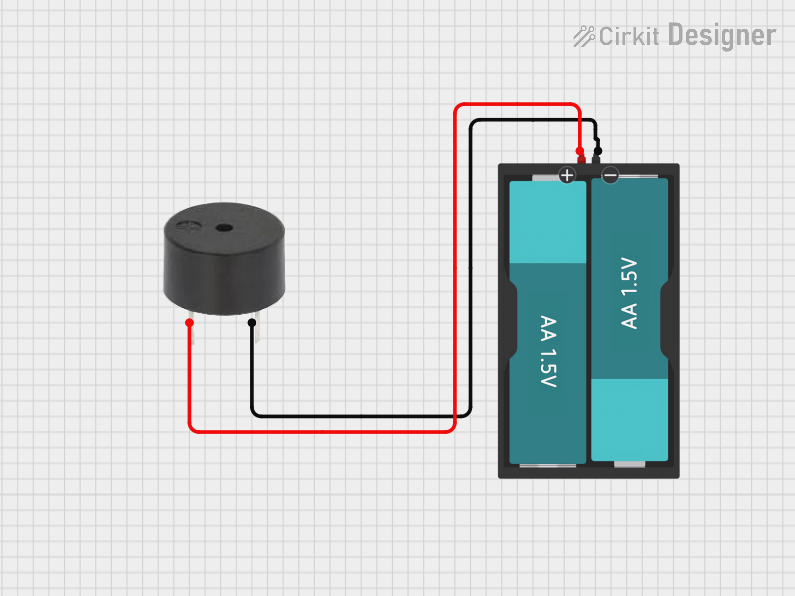
  1. Power Connection: Connect the positive terminal of the buzzer to the positive voltage supply (3-24V DC) and the negative terminal to the ground (GND).
  2. Control with a Microcontroller: The buzzer can be controlled using a microcontroller (e.g., Arduino UNO) by connecting the positive terminal to a digital output pin and the negative terminal to GND. Use a current-limiting resistor if necessary to protect the microcontroller pin.
  3. Direct Power: For simple applications, the buzzer can be directly powered by a DC voltage source within its operating range.

Important Considerations and Best Practices

  • Voltage Range: Ensure the supply voltage is within the specified range (3-24V). Exceeding this range may damage the buzzer.
  • Polarity: Always connect the positive and negative terminals correctly. Reversing polarity may prevent the buzzer from functioning.
  • Mounting: Secure the buzzer in place to avoid vibrations or movement that could affect sound quality.
  • Noise Sensitivity: Place the buzzer away from sensitive components to avoid interference caused by its sound vibrations.

Example: Using the 3-24V Buzzer with an Arduino UNO

The following example demonstrates how to connect and control the buzzer using an Arduino UNO. The buzzer will emit a sound when the Arduino sends a HIGH signal to the connected pin.

// Example: Controlling a 3-24V Buzzer with Arduino UNO

// Define the pin connected to the buzzer
const int buzzerPin = 8;

void setup() {
  // Set the buzzer pin as an output
  pinMode(buzzerPin, OUTPUT);
}

void loop() {
  // Turn the buzzer ON
  digitalWrite(buzzerPin, HIGH);
  delay(1000); // Keep the buzzer ON for 1 second

  // Turn the buzzer OFF
  digitalWrite(buzzerPin, LOW);
  delay(1000); // Keep the buzzer OFF for 1 second
}

Troubleshooting and FAQs

Common Issues and Solutions

  1. No Sound from the Buzzer:

    • Cause: Incorrect polarity or insufficient voltage.
    • Solution: Verify the connections and ensure the supply voltage is within the 3-24V range.
  2. Buzzer Produces Weak or Distorted Sound:

    • Cause: Low supply voltage or poor connections.
    • Solution: Check the power supply and ensure secure connections to the terminals.
  3. Buzzer Does Not Turn Off:

    • Cause: The control signal from the microcontroller is stuck at HIGH.
    • Solution: Check the microcontroller code and ensure the pin controlling the buzzer is toggling correctly.
  4. Interference with Other Components:

    • Cause: Sound vibrations or electromagnetic interference.
    • Solution: Place the buzzer away from sensitive components and use proper shielding if necessary.

FAQs

  • Q: Can I use the buzzer with an AC power source?
    A: No, the 3-24V buzzer is designed for DC operation only. Using AC power may damage the component.

  • Q: Do I need an external driver circuit for this buzzer?
    A: No, this is an active buzzer, so it does not require an external driver circuit. It produces sound when powered directly.

  • Q: Can I adjust the sound frequency of the buzzer?
    A: No, the frequency of an active buzzer is fixed. For adjustable frequency, consider using a passive buzzer with a signal generator.

  • Q: Is the buzzer waterproof?
    A: Most 3-24V buzzers are not waterproof. Check the datasheet of your specific model for environmental ratings.