
How to Use BLOWER FAN 12V: Examples, Pinouts, and Specs
 Design with BLOWER FAN 12V in Cirkit Designer
Introduction
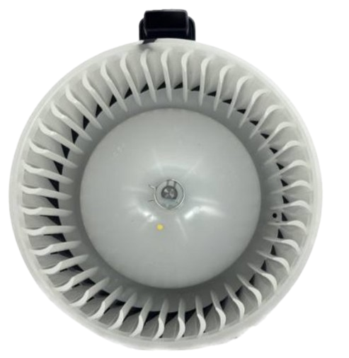
A 12V blower fan is an electric fan designed to move air or gas in a circuit, typically used for cooling or ventilation in electronic devices and enclosures. Unlike traditional axial fans, blower fans use a centrifugal design to generate higher static pressure, making them ideal for applications where airflow needs to be directed through ducts or confined spaces.
Explore Projects Built with BLOWER FAN 12V
 Open Project in Cirkit Designer
 Open Project in Cirkit Designer
 Open Project in Cirkit Designer
 Open Project in Cirkit Designer
Explore Projects Built with BLOWER FAN 12V
Open Project in Cirkit DesignerOpen Project in Cirkit DesignerOpen Project in Cirkit DesignerOpen Project in Cirkit DesignerCommon Applications and Use Cases
- Cooling electronic components such as CPUs, GPUs, and power supplies
- Ventilation in 3D printers, laser cutters, and other enclosed systems
- Air circulation in small HVAC systems or air purifiers
- Removing heat from compact enclosures or cabinets
- Supporting airflow in robotics and DIY projects
Technical Specifications
Below are the key technical details for a standard 12V blower fan:
| Parameter | Specification |
|---|---|
| Operating Voltage | 12V DC |
| Current Consumption | 0.15A to 0.5A (varies by model) |
| Power Consumption | 1.8W to 6W |
| Airflow | 5 CFM to 15 CFM (Cubic Feet per Minute) |
| Static Pressure | 5 mmH2O to 15 mmH2O |
| Noise Level | 25 dBA to 45 dBA |
| Dimensions | Varies (e.g., 50x50x15mm, 75x75x30mm) |
| Bearing Type | Sleeve or Ball Bearing |
| Connector Type | 2-pin or 3-pin |
| Lifespan | 30,000 to 50,000 hours |
Pin Configuration and Descriptions
The pin configuration for a typical 12V blower fan is as follows:
| Pin | Name | Description |
|---|---|---|
| 1 | VCC (+) | Positive power supply (12V DC) |
| 2 | GND (-) | Ground connection |
| 3* | Tachometer (T) | Optional pin for RPM feedback (only on 3-pin models) |
* Note: The tachometer pin is only available on 3-pin blower fans and provides a pulse signal for monitoring fan speed.
Usage Instructions
How to Use the Component in a Circuit
- Power Supply: Connect the VCC pin to a 12V DC power source and the GND pin to ground. Ensure the power supply can provide sufficient current for the fan's operation.
- Optional RPM Monitoring: If using a 3-pin blower fan, connect the tachometer pin to a microcontroller or monitoring circuit to measure fan speed.
- Mounting: Secure the blower fan in place using screws or adhesive mounts. Ensure the airflow direction aligns with your cooling or ventilation requirements (usually indicated by arrows on the fan housing).
- Wiring: Use appropriate gauge wires to handle the current without significant voltage drop.
Important Considerations and Best Practices
- Voltage Tolerance: Ensure the input voltage does not exceed 12V DC to avoid damaging the fan.
- Current Rating: Verify that your power supply can handle the fan's current draw, especially during startup, which may briefly exceed the rated current.
- Airflow Path: Avoid obstructing the intake or exhaust of the fan to maintain optimal airflow.
- Noise Reduction: Use rubber mounts or grommets to minimize vibration and noise.
- Heat Dissipation: Ensure the fan is not exposed to excessive heat beyond its operating temperature range (typically -10°C to 70°C).
Example: Connecting to an Arduino UNO
A 12V blower fan can be controlled using an Arduino UNO and a transistor or MOSFET. Below is an example circuit and code to control the fan speed using PWM (Pulse Width Modulation):
Circuit Diagram
- Connect the fan's VCC pin to a 12V power supply.
- Connect the fan's GND pin to the source pin of an N-channel MOSFET.
- Connect the MOSFET's drain pin to the fan's GND pin.
- Connect the MOSFET's gate pin to Arduino pin 9 through a 220-ohm resistor.
- Connect a 10k-ohm pull-down resistor between the MOSFET's gate and source pins.
Arduino Code
// Arduino code to control a 12V blower fan using PWM
// Ensure the fan is connected to a 12V power supply and controlled via a MOSFET

const int fanPin = 9; // PWM pin connected to the MOSFET gate

void setup() {
  pinMode(fanPin, OUTPUT); // Set the fan control pin as an output
}

void loop() {
  // Gradually increase fan speed
  for (int speed = 0; speed <= 255; speed += 5) {
    analogWrite(fanPin, speed); // Set PWM duty cycle (0-255)
    delay(50); // Wait 50ms before increasing speed
  }

  delay(2000); // Run at full speed for 2 seconds

  // Gradually decrease fan speed
  for (int speed = 255; speed >= 0; speed -= 5) {
    analogWrite(fanPin, speed); // Set PWM duty cycle (0-255)
    delay(50); // Wait 50ms before decreasing speed
  }

  delay(2000); // Fan off for 2 seconds before repeating
}
Troubleshooting and FAQs
Common Issues Users Might Face
Fan Not Spinning:
- Check the power supply voltage and current rating.
- Verify the wiring connections, especially the VCC and GND pins.
- Ensure the fan is not physically obstructed.
Excessive Noise or Vibration:
- Inspect for loose mounting or debris inside the fan.
- Use rubber mounts to reduce vibration.
Fan Speed Not Controllable:
- Ensure the PWM signal is correctly configured (for 3-pin fans).
- Verify the MOSFET or transistor is functioning properly.
Overheating:
- Check for airflow obstructions.
- Ensure the fan is operating within its rated voltage and current limits.
Solutions and Tips for Troubleshooting
- Use a multimeter to measure the voltage at the fan's VCC and GND pins.
- Test the fan with a direct 12V DC power source to rule out circuit issues.
- If using a 3-pin fan, monitor the tachometer output with an oscilloscope or microcontroller to verify RPM feedback.
By following this documentation, you can effectively integrate and troubleshoot a 12V blower fan in your projects.