How to Use BTS7960 (IBT-2) Motor Driver: Examples, Pinouts, and Specs
Introduction
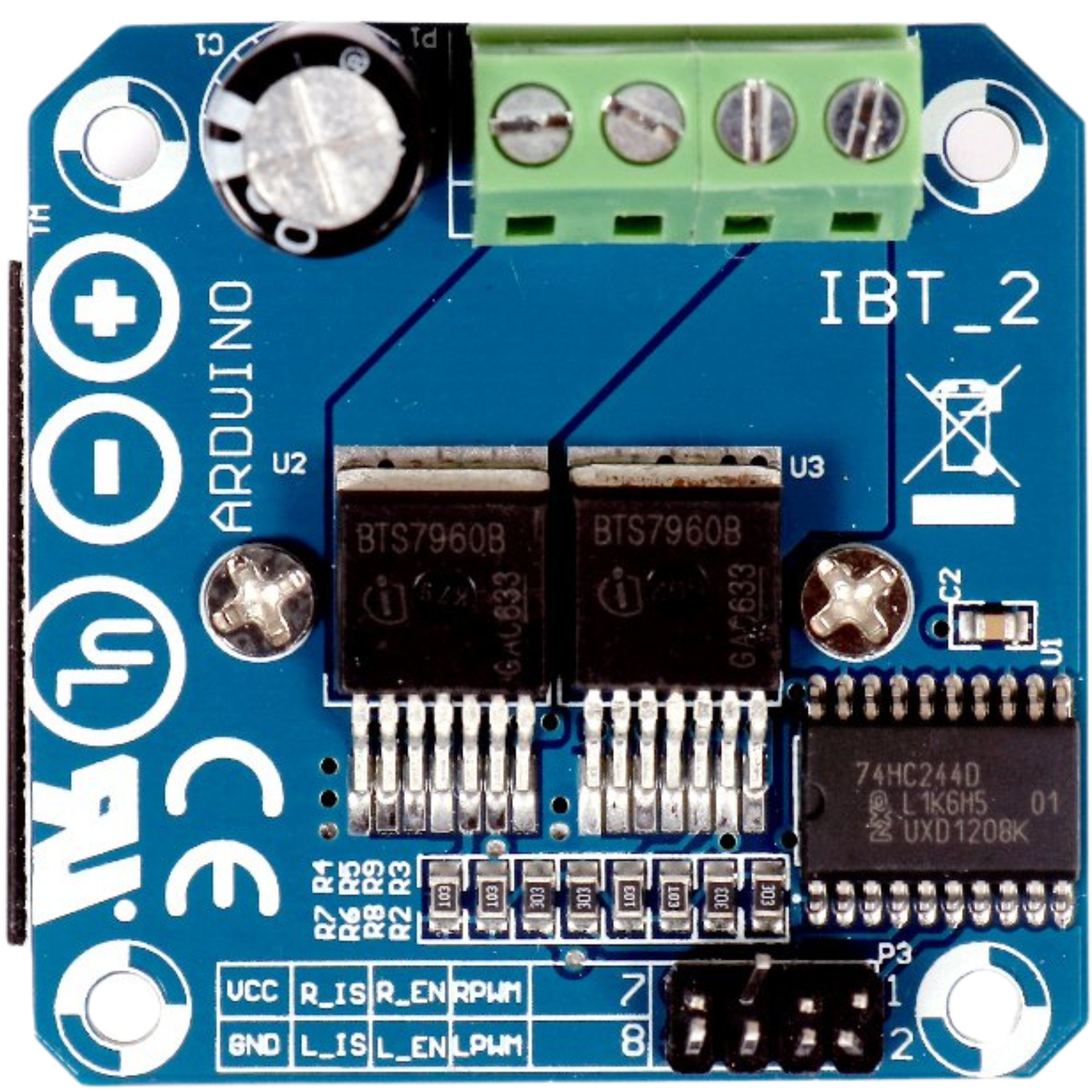
The BTS7960 (commonly referred to as the IBT-2) is a high-current H-bridge motor driver designed for controlling DC motors. It is capable of handling high currents (up to 43A) and supports Pulse Width Modulation (PWM) signals for precise motor speed and direction control. The module features built-in protection mechanisms, including overcurrent and thermal overload protection, making it a reliable choice for demanding motor control applications.
Explore Projects Built with BTS7960 (IBT-2) Motor Driver

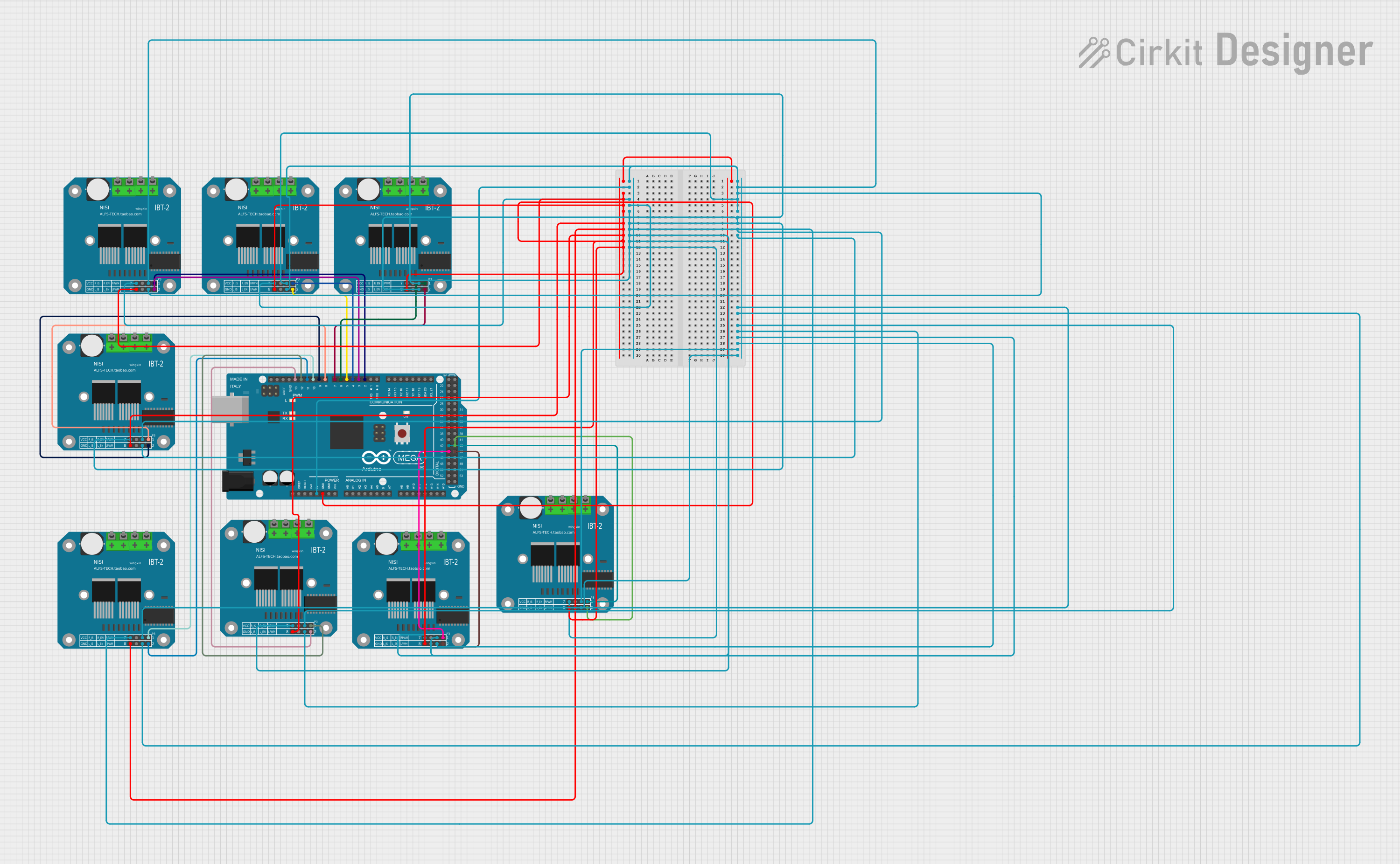
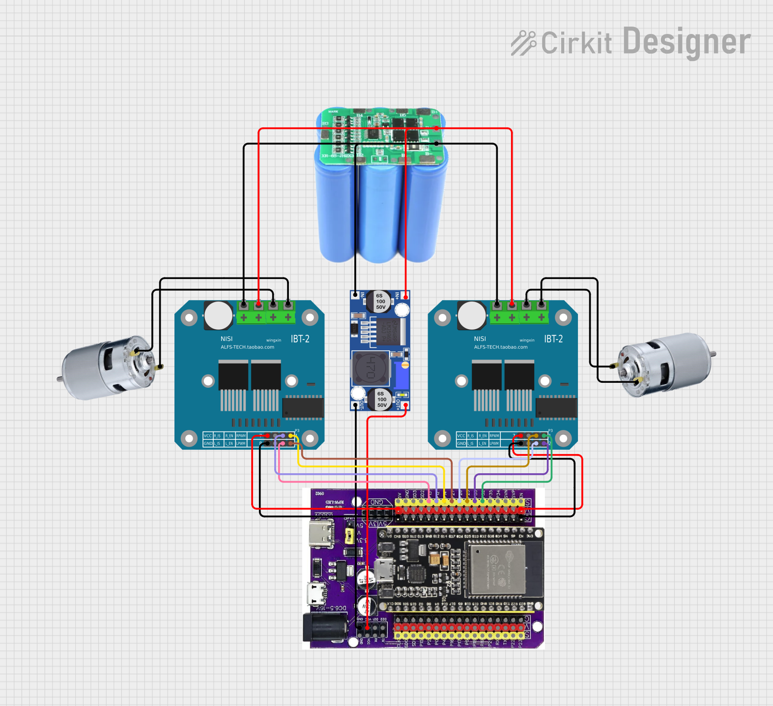
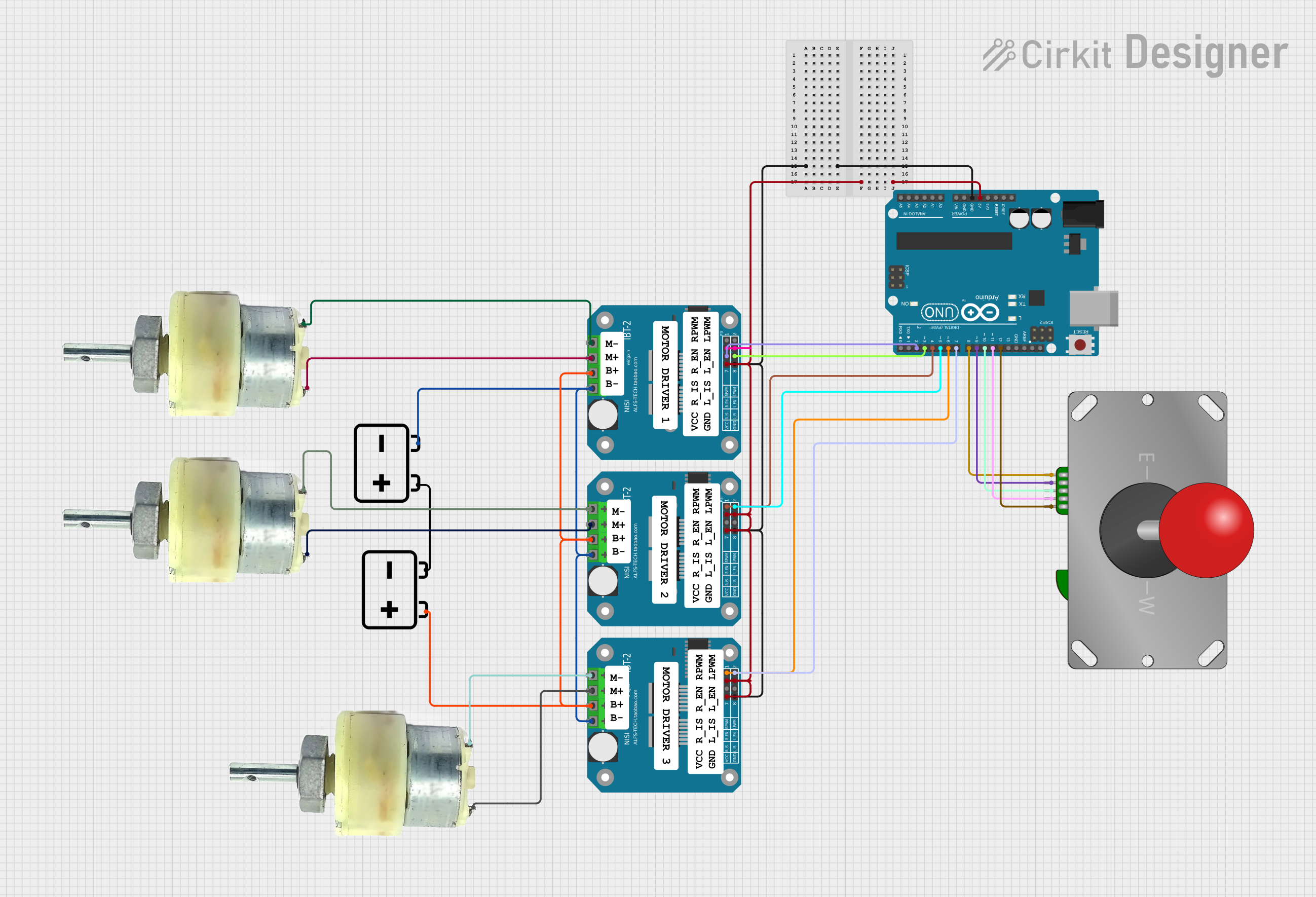
Explore Projects Built with BTS7960 (IBT-2) Motor Driver
Common Applications and Use Cases
- Robotics and automation systems
- Electric vehicles and motorized carts
- Conveyor belts and industrial machinery
- Remote-controlled cars, boats, and drones
- DIY projects requiring high-current motor control
Technical Specifications
The BTS7960 motor driver module is designed to handle high-power DC motors efficiently. Below are its key technical details:
| Parameter | Value |
|---|---|
| Operating Voltage | 5V logic, 6V–27V motor supply |
| Maximum Continuous Current | 43A |
| Peak Current | 50A |
| PWM Frequency | Up to 25kHz |
| Logic Level Input Voltage | 3.3V or 5V |
| Overcurrent Protection | Yes |
| Thermal Shutdown | Yes |
| Dimensions | 43mm x 45mm x 28mm |
Pin Configuration and Descriptions
The BTS7960 module has a total of 8 pins for interfacing with a microcontroller and motor. Below is the pinout:
| Pin Name | Type | Description |
|---|---|---|
| VCC | Power Input | 5V logic power supply for the module |
| GND | Ground | Common ground for logic and motor power |
| RPWM | Input | PWM signal for controlling motor rotation in one direction |
| LPWM | Input | PWM signal for controlling motor rotation in the opposite direction |
| R_EN | Input | Enable pin for the right half-bridge (active HIGH) |
| L_EN | Input | Enable pin for the left half-bridge (active HIGH) |
| MOTOR+ | Output | Positive terminal of the motor |
| MOTOR- | Output | Negative terminal of the motor |
Usage Instructions
How to Use the BTS7960 in a Circuit
Power Connections:
- Connect the motor power supply (6V–27V) to the
MOTOR+andMOTOR-terminals. - Provide a 5V logic power supply to the
VCCpin and connect theGNDpin to the ground of your microcontroller.
- Connect the motor power supply (6V–27V) to the
Control Connections:
- Connect the
RPWMandLPWMpins to PWM-capable pins on your microcontroller. - Use the
R_ENandL_ENpins to enable or disable the respective half-bridges.
- Connect the
Motor Control:
- To rotate the motor in one direction, send a PWM signal to
RPWMwhile keepingLPWMLOW. - To rotate the motor in the opposite direction, send a PWM signal to
LPWMwhile keepingRPWMLOW. - Adjust the duty cycle of the PWM signal to control the motor speed.
- To rotate the motor in one direction, send a PWM signal to
Important Considerations and Best Practices
- Ensure the motor power supply voltage is within the specified range (6V–27V).
- Use a heat sink or cooling fan if operating at high currents for extended periods.
- Avoid shorting the motor terminals, as this may damage the module.
- Always connect the ground of the motor driver to the ground of the microcontroller.
Example Code for Arduino UNO
Below is an example of how to control a DC motor using the BTS7960 with an Arduino UNO:
// Define pin connections for the BTS7960 motor driver
const int RPWM = 9;  // PWM pin for forward rotation
const int LPWM = 10; // PWM pin for reverse rotation
const int R_EN = 7;  // Enable pin for right half-bridge
const int L_EN = 8;  // Enable pin for left half-bridge

void setup() {
  // Set pin modes
  pinMode(RPWM, OUTPUT);
  pinMode(LPWM, OUTPUT);
  pinMode(R_EN, OUTPUT);
  pinMode(L_EN, OUTPUT);

  // Enable both half-bridges
  digitalWrite(R_EN, HIGH);
  digitalWrite(L_EN, HIGH);
}

void loop() {
  // Rotate motor forward at 50% speed
  analogWrite(RPWM, 128); // 50% duty cycle (128 out of 255)
  analogWrite(LPWM, 0);   // LPWM set to LOW
  delay(2000);            // Run for 2 seconds

  // Stop the motor
  analogWrite(RPWM, 0);
  analogWrite(LPWM, 0);
  delay(1000);            // Pause for 1 second

  // Rotate motor backward at 75% speed
  analogWrite(RPWM, 0);   // RPWM set to LOW
  analogWrite(LPWM, 192); // 75% duty cycle (192 out of 255)
  delay(2000);            // Run for 2 seconds

  // Stop the motor
  analogWrite(RPWM, 0);
  analogWrite(LPWM, 0);
  delay(1000);            // Pause for 1 second
}
Troubleshooting and FAQs
Common Issues and Solutions
Motor Does Not Rotate:
- Ensure the motor power supply is connected and within the specified voltage range.
- Verify that the
R_ENandL_ENpins are set HIGH to enable the half-bridges. - Check the PWM signal connections and ensure the duty cycle is not set to 0.
Overheating:
- Use a heat sink or cooling fan to dissipate heat during high-current operation.
- Reduce the motor load if possible.
Erratic Motor Behavior:
- Ensure a common ground connection between the motor driver and the microcontroller.
- Check for loose or faulty wiring.
Module Shuts Down Unexpectedly:
- This may be due to overcurrent or thermal protection. Reduce the motor load or improve cooling.
FAQs
Q: Can the BTS7960 control two motors simultaneously?
A: No, the BTS7960 is a single H-bridge driver and can control only one motor at a time.
Q: What is the maximum PWM frequency supported?
A: The module supports PWM frequencies up to 25kHz.
Q: Can I use a 3.3V microcontroller with the BTS7960?
A: Yes, the logic input pins are compatible with both 3.3V and 5V signals.
Q: Is it safe to use the BTS7960 without a heat sink?
A: For low-current applications, it may be safe, but for high-current usage, a heat sink or cooling fan is recommended.