
How to Use Header 4: Examples, Pinouts, and Specs
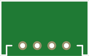
 Design with Header 4 in Cirkit Designer
Introduction
- A Header 4 is a type of connector used in electronic circuits, typically featuring four pins for connecting wires or other components. It is designed to facilitate easy and reliable connections between different parts of a circuit.
- Common applications include signal transmission, power distribution, and interfacing with microcontrollers or other modules. Header 4 connectors are widely used in prototyping, PCB designs, and embedded systems.
Explore Projects Built with Header 4
 Open Project in Cirkit Designer
 Open Project in Cirkit Designer
 Open Project in Cirkit Designer
 Open Project in Cirkit Designer
Explore Projects Built with Header 4
Open Project in Cirkit DesignerOpen Project in Cirkit DesignerOpen Project in Cirkit DesignerOpen Project in Cirkit DesignerTechnical Specifications
- Type: Male or Female Header (Straight or Right-Angle)
- Number of Pins: 4
- Pin Pitch: 2.54 mm (standard), though other pitches may exist
- Current Rating: Typically 1A to 3A per pin (varies by manufacturer)
- Voltage Rating: Up to 250V (varies by manufacturer)
- Material:
- Pins: Tin-plated or gold-plated copper
- Housing: Plastic (e.g., PBT or Nylon)
- Operating Temperature: -40°C to +105°C (typical)
Pin Configuration and Descriptions
The Header 4 connector has four pins, which can be used for various purposes depending on the circuit design. Below is a general example of pin usage:
| Pin Number | Description | Typical Use |
|---|---|---|
| 1 | VCC (Power Supply) | Supplies power to the circuit |
| 2 | GND (Ground) | Common ground connection |
| 3 | Signal/Data Line 1 | Transmits or receives data |
| 4 | Signal/Data Line 2 | Transmits or receives data |
Note: The pin configuration may vary depending on the specific application or circuit design. Always refer to the schematic or datasheet for your project.
Usage Instructions
Connecting the Header 4:
- Align the pins of the Header 4 with the corresponding holes or connectors on the PCB or breadboard.
- Ensure proper orientation to avoid incorrect connections.
- Solder the pins to the PCB for a permanent connection, or use a female header for a removable connection.
Important Considerations:
- Verify the pinout of the Header 4 before connecting it to avoid damaging components.
- Ensure the current and voltage ratings of the Header 4 match the requirements of your circuit.
- Use heat shrink tubing or insulation to prevent accidental short circuits if wires are directly connected to the pins.
Example: Using Header 4 with an Arduino UNO: Below is an example of connecting a Header 4 to an Arduino UNO for interfacing with a sensor or module.
// Example: Reading data from a sensor connected via Header 4 const int dataPin1 = 2; // Pin 3 of Header 4 connected to Arduino pin 2 const int dataPin2 = 3; // Pin 4 of Header 4 connected to Arduino pin 3 void setup() { pinMode(dataPin1, INPUT); // Set dataPin1 as input pinMode(dataPin2, INPUT); // Set dataPin2 as input Serial.begin(9600); // Initialize serial communication } void loop() { int sensorValue1 = digitalRead(dataPin1); // Read data from pin 3 of Header 4 int sensorValue2 = digitalRead(dataPin2); // Read data from pin 4 of Header 4 // Print the sensor values to the Serial Monitor Serial.print("Sensor 1: "); Serial.println(sensorValue1); Serial.print("Sensor 2: "); Serial.println(sensorValue2); delay(1000); // Wait for 1 second before reading again }Note: Ensure that the sensor or module connected to the Header 4 is compatible with the Arduino UNO's voltage levels (e.g., 5V or 3.3V).
Troubleshooting and FAQs
Common Issues
Loose Connections:
- Problem: The Header 4 pins are not making proper contact with the PCB or connector.
- Solution: Ensure the pins are securely soldered or properly inserted into the female header.
Incorrect Pinout:
- Problem: The pins are connected in the wrong order, causing the circuit to malfunction.
- Solution: Double-check the pinout and wiring against the circuit schematic.
Overcurrent or Overvoltage:
- Problem: The Header 4 is damaged due to exceeding its current or voltage ratings.
- Solution: Verify the ratings of the Header 4 and ensure the circuit operates within safe limits.
Signal Interference:
- Problem: Data transmission is unreliable due to noise or interference.
- Solution: Use shorter wires, shielded cables, or add pull-up/pull-down resistors as needed.
FAQs
Q: Can I use a Header 4 for both power and data connections?
- A: Yes, a Header 4 can be used for both power and data connections, but ensure the pins are properly assigned and insulated to prevent short circuits.
Q: What tools are needed to solder a Header 4 onto a PCB?
- A: You will need a soldering iron, solder wire, and optionally flux for better solder flow. A desoldering pump or wick can be used for corrections.
Q: Can I use a Header 4 with a breadboard?
- A: Yes, a male Header 4 can be directly inserted into a breadboard, while a female Header 4 can be used to connect wires or components.
Q: How do I prevent accidental disconnections?
- A: Use locking connectors or secure the Header 4 with hot glue or cable ties if necessary.
By following this documentation, you can effectively use a Header 4 in your electronic projects while avoiding common pitfalls.