How to Use Limit switch: Examples, Pinouts, and Specs
Introduction
A limit switch is an electromechanical device that detects the presence or absence of an object or the position of a moving part. It is widely used in industrial and mechanical systems to control machinery or equipment. The switch operates by making or breaking an electrical connection when a physical object comes into contact with its actuator.
Explore Projects Built with Limit switch
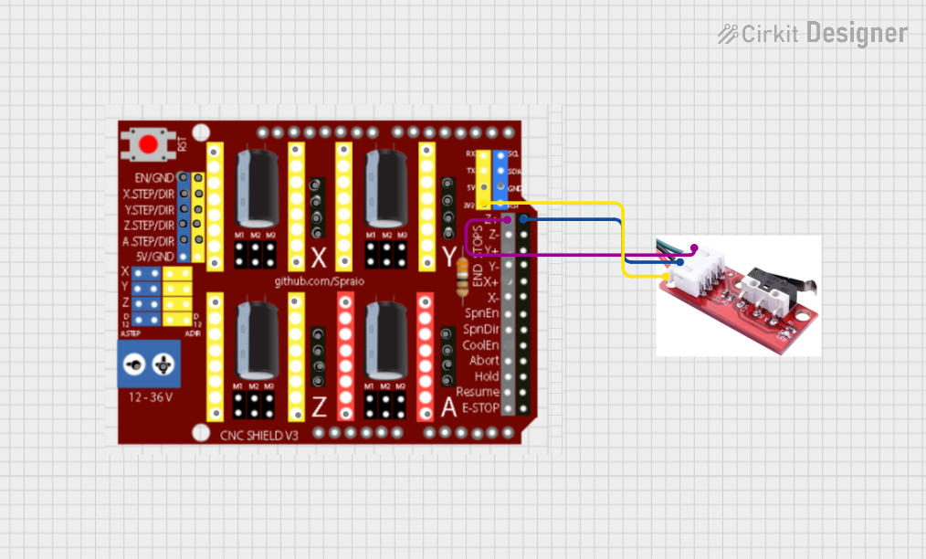
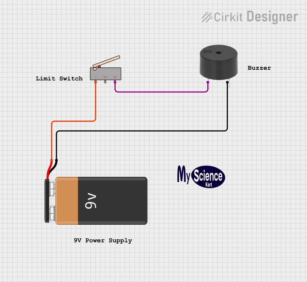
Explore Projects Built with Limit switch
Common Applications and Use Cases
- Detecting the position of moving parts in machinery
- Safety interlocks in industrial equipment
- End-stop detection in CNC machines, 3D printers, and robotics
- Monitoring the opening and closing of doors or hatches
- Automated conveyor systems for object detection
Technical Specifications
Key Technical Details
- Operating Voltage: Typically 5V to 250V AC/DC (varies by model)
- Current Rating: 5A to 15A (depending on the switch type)
- Contact Configuration: Normally Open (NO), Normally Closed (NC), or both
- Actuator Types: Roller lever, plunger, or whisker
- Mechanical Durability: Up to 10 million operations (varies by model)
- Operating Temperature: -25°C to 80°C (typical range)
Pin Configuration and Descriptions
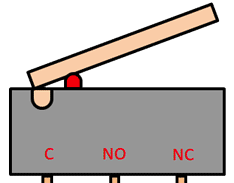
The pin configuration of a limit switch depends on its contact type. Below is a general description for a common 3-terminal limit switch:
| Pin Name | Description |
|---|---|
| COM | Common terminal, connected to the moving contact inside the switch |
| NO | Normally Open terminal, connected to COM when the actuator is engaged |
| NC | Normally Closed terminal, connected to COM when the actuator is not engaged |
Usage Instructions
How to Use the Component in a Circuit
- Identify the Terminals: Locate the COM, NO, and NC terminals on the limit switch.
- Connect the Circuit:
- For a Normally Open (NO) configuration, connect one wire to the COM terminal and another to the NO terminal. The circuit will close when the actuator is engaged.
- For a Normally Closed (NC) configuration, connect one wire to the COM terminal and another to the NC terminal. The circuit will open when the actuator is engaged.
- Mount the Switch: Secure the limit switch in the desired position so that the actuator interacts with the moving part or object.
- Test the Operation: Verify that the switch operates as expected by manually engaging the actuator.
Important Considerations and Best Practices
- Voltage and Current Ratings: Ensure the switch is rated for the voltage and current in your circuit to avoid damage or failure.
- Debouncing: When using the switch with microcontrollers, implement software or hardware debouncing to handle signal noise caused by mechanical contact bounce.
- Actuator Alignment: Properly align the actuator with the moving part to ensure reliable operation.
- Environmental Protection: Use a switch with an appropriate IP rating if it will be exposed to dust, moisture, or other harsh conditions.
Example: Connecting a Limit Switch to an Arduino UNO
Below is an example of how to connect and use a limit switch with an Arduino UNO:
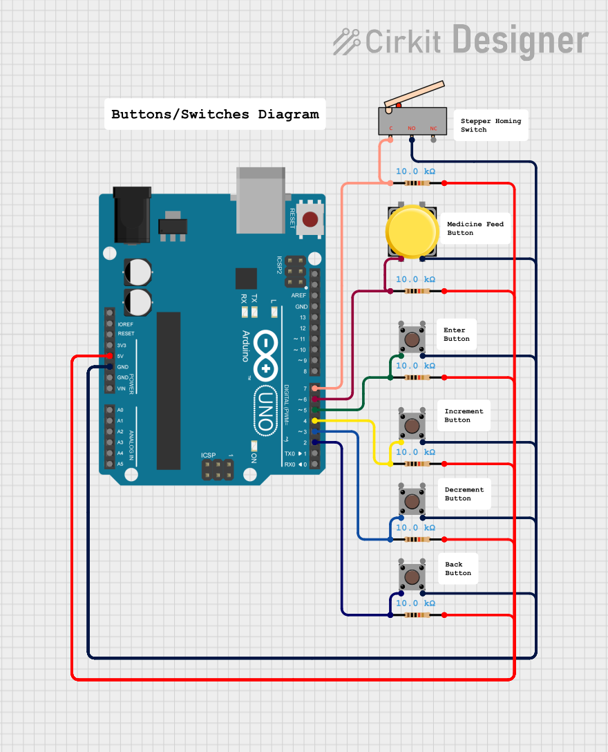
Circuit Diagram
- Connect the COM terminal of the limit switch to the GND pin of the Arduino.
- Connect the NO terminal of the limit switch to digital pin 2 of the Arduino.
- Use a pull-up resistor (10kΩ) between digital pin 2 and the 5V pin of the Arduino.
Arduino Code
// Define the pin connected to the limit switch
const int limitSwitchPin = 2;

// Variable to store the state of the limit switch
int switchState = 0;

void setup() {
  // Set the limit switch pin as input with an internal pull-up resistor
  pinMode(limitSwitchPin, INPUT_PULLUP);

  // Initialize serial communication for debugging
  Serial.begin(9600);
}

void loop() {
  // Read the state of the limit switch
  switchState = digitalRead(limitSwitchPin);

  // Check if the switch is pressed (LOW state due to pull-up resistor)
  if (switchState == LOW) {
    Serial.println("Limit switch is engaged!");
  } else {
    Serial.println("Limit switch is not engaged.");
  }

  // Add a small delay to avoid spamming the serial monitor
  delay(200);
}
Troubleshooting and FAQs
Common Issues and Solutions
Switch Not Responding:
- Cause: Incorrect wiring or loose connections.
- Solution: Double-check the wiring and ensure all connections are secure.
False Triggering:
- Cause: Mechanical contact bounce or electrical noise.
- Solution: Implement debouncing in software or use a capacitor for hardware debouncing.
Actuator Not Engaging:
- Cause: Misalignment of the actuator and the moving part.
- Solution: Adjust the position of the switch to ensure proper engagement.
Switch Damaged:
- Cause: Exceeding voltage or current ratings.
- Solution: Replace the switch and ensure the new one matches the circuit's requirements.
FAQs
Q: Can I use a limit switch with AC circuits?
A: Yes, many limit switches are rated for both AC and DC circuits. Check the specifications of your switch to confirm compatibility.
Q: How do I protect the switch in harsh environments?
A: Use a limit switch with a high IP rating (e.g., IP67) for protection against dust and water.
Q: Can I use multiple limit switches in a single circuit?
A: Yes, you can wire multiple switches in series or parallel, depending on your application requirements.
Q: What is the difference between NO and NC configurations?
A: In a Normally Open (NO) configuration, the circuit is open until the actuator is engaged. In a Normally Closed (NC) configuration, the circuit is closed until the actuator is engaged.