How to Use 10 Pin Node: Examples, Pinouts, and Specs

Introduction
The 10 Pin Node is a versatile connector or interface designed to facilitate the connection of multiple wires or components within a circuit. It is commonly used for signal or power distribution, making it an essential component in various electronic systems. Its compact design and ability to handle multiple connections simultaneously make it ideal for applications requiring efficient wiring and organization.
Explore Projects Built with 10 Pin Node
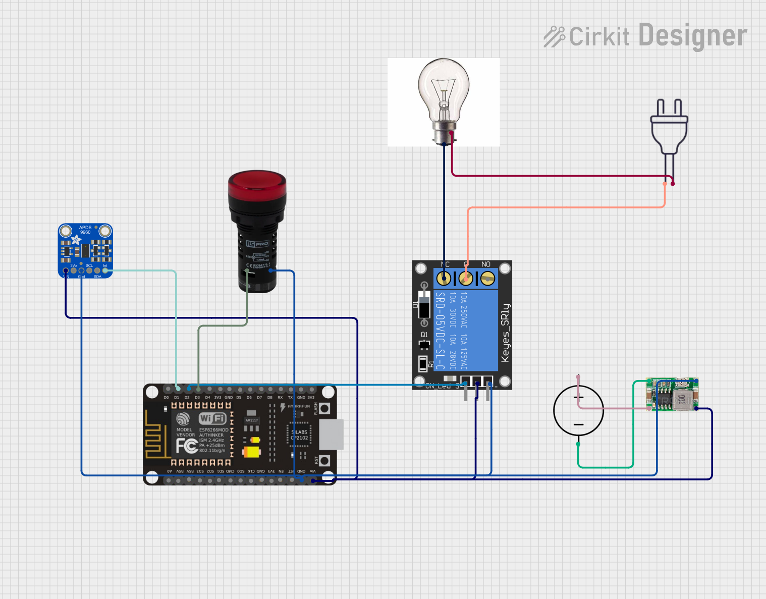


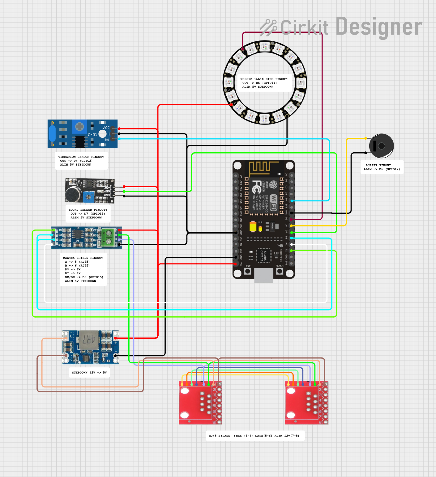
Explore Projects Built with 10 Pin Node
Common Applications and Use Cases
- Signal distribution in microcontroller-based projects
- Power distribution in low-voltage circuits
- Prototyping and testing of electronic circuits
- Interfacing sensors, actuators, or modules with a central controller
- Use in robotics, IoT devices, and embedded systems
Technical Specifications
Key Technical Details
- Number of Pins: 10
- Voltage Rating: Up to 30V DC (varies by model)
- Current Rating: Typically 1A to 3A per pin
- Pin Spacing: 2.54mm (standard pitch)
- Connector Type: Male or female headers, or screw terminals (depending on the model)
- Material: Plastic housing with metal pins (usually tin or gold-plated for durability)
- Operating Temperature Range: -40°C to 85°C
Pin Configuration and Descriptions
The 10 Pin Node typically consists of 10 pins arranged in a single row or dual rows. Below is a general description of the pin configuration:
| Pin Number | Description | Notes |
|---|---|---|
| 1 | Signal/Power Input | Connect to the power source or signal |
| 2 | Ground (GND) | Common ground for the circuit |
| 3 | Signal/Power Output | Distributes signal or power |
| 4 | Signal/Power Output | Distributes signal or power |
| 5 | Signal/Power Output | Distributes signal or power |
| 6 | Signal/Power Output | Distributes signal or power |
| 7 | Signal/Power Output | Distributes signal or power |
| 8 | Signal/Power Output | Distributes signal or power |
| 9 | Signal/Power Output | Distributes signal or power |
| 10 | Signal/Power Output | Distributes signal or power |
Note: The exact pin configuration may vary depending on the specific model of the 10 Pin Node. Always refer to the manufacturer's datasheet for precise details.
Usage Instructions
How to Use the 10 Pin Node in a Circuit
- Identify the Pin Configuration: Refer to the pinout table or datasheet to understand the function of each pin.
- Connect the Input: Attach the signal or power source to the designated input pin (e.g., Pin 1).
- Connect the Outputs: Use the output pins (e.g., Pins 3-10) to distribute the signal or power to other components in the circuit.
- Secure Connections: If using a screw terminal version, tighten the screws to ensure a secure connection. For header versions, ensure proper alignment and insertion.
- Test the Circuit: Verify that all connections are correct and that the circuit functions as intended.
Important Considerations and Best Practices
- Avoid Overloading: Ensure that the current drawn by connected components does not exceed the current rating of the 10 Pin Node.
- Check Voltage Compatibility: Verify that the voltage applied to the node is within its rated range.
- Prevent Short Circuits: Double-check connections to avoid accidental shorts between pins.
- Use Proper Tools: Use appropriate tools (e.g., screwdrivers for screw terminals or soldering equipment for header pins) to make reliable connections.
- Label Connections: For complex circuits, label the wires connected to each pin to avoid confusion during troubleshooting.
Example: Connecting a 10 Pin Node to an Arduino UNO
Below is an example of how to use a 10 Pin Node to distribute power and signals to multiple components connected to an Arduino UNO.
Circuit Description
- Pin 1: Connected to the 5V output of the Arduino UNO.
- Pin 2: Connected to the GND of the Arduino UNO.
- Pins 3-10: Connected to various sensors or modules.
Sample Code
// Example code for using a 10 Pin Node with an Arduino UNO
// This code reads data from a sensor connected to Pin 3 of the 10 Pin Node
// and controls an LED connected to Pin 4 of the 10 Pin Node.

const int sensorPin = A0; // Sensor connected to Pin 3 (analog input A0)
const int ledPin = 9;     // LED connected to Pin 4 (digital pin 9)

void setup() {
  pinMode(ledPin, OUTPUT); // Set LED pin as output
  Serial.begin(9600);      // Initialize serial communication
}

void loop() {
  int sensorValue = analogRead(sensorPin); // Read sensor value
  Serial.println(sensorValue);            // Print sensor value to Serial Monitor

  // Turn on LED if sensor value exceeds threshold
  if (sensorValue > 500) {
    digitalWrite(ledPin, HIGH); // Turn on LED
  } else {
    digitalWrite(ledPin, LOW);  // Turn off LED
  }

  delay(100); // Small delay for stability
}
Troubleshooting and FAQs
Common Issues and Solutions
Loose Connections:
- Issue: Components connected to the 10 Pin Node are not functioning.
- Solution: Check all connections to ensure they are secure. Tighten screws or reinsert header pins as needed.
Overheating:
- Issue: The 10 Pin Node becomes hot during operation.
- Solution: Ensure that the current drawn by connected components does not exceed the node's current rating. Reduce the load or use a higher-rated connector if necessary.
Signal Interference:
- Issue: Signals distributed through the 10 Pin Node are noisy or distorted.
- Solution: Use shorter wires to minimize interference. Consider adding decoupling capacitors to stabilize the signal.
Incorrect Pin Usage:
- Issue: Components are not receiving power or signals as expected.
- Solution: Verify the pin configuration and ensure that each component is connected to the correct pin.
FAQs
Q: Can the 10 Pin Node handle AC power?
A: Most 10 Pin Nodes are designed for DC circuits. Check the manufacturer's specifications before using with AC power.Q: Can I use the 10 Pin Node for high-current applications?
A: The current rating is typically 1A to 3A per pin. For higher currents, consider using a connector with a higher rating.Q: How do I clean the 10 Pin Node?
A: Use a soft brush or compressed air to remove dust. Avoid using water or cleaning agents that may damage the pins.
By following this documentation, you can effectively integrate the 10 Pin Node into your electronic projects and ensure reliable performance.