How to Use ESP 32: Examples, Pinouts, and Specs
Introduction
The ESP32 is a low-cost, low-power system on a chip (SoC) developed by Espressif Systems. It features integrated Wi-Fi and Bluetooth capabilities, making it an ideal choice for Internet of Things (IoT) applications, smart devices, and embedded systems. The ESP32 is highly versatile, offering dual-core processing, a wide range of GPIO pins, and support for various communication protocols.
Explore Projects Built with ESP 32


Explore Projects Built with ESP 32
Common Applications and Use Cases
- IoT devices (e.g., smart home systems, environmental monitoring)
- Wireless communication (Wi-Fi and Bluetooth)
- Wearable devices
- Robotics and automation
- Data logging and remote sensing
- Prototyping and development of embedded systems
Technical Specifications
The ESP32 is packed with features that make it a powerful and flexible component for a wide range of applications. Below are its key technical specifications:
Key Technical Details
- Processor: Dual-core Xtensa® 32-bit LX6 microprocessor
- Clock Speed: Up to 240 MHz
- RAM: 520 KB SRAM
- Flash Memory: Typically 4 MB (varies by module)
- Wi-Fi: 802.11 b/g/n (2.4 GHz)
- Bluetooth: v4.2 BR/EDR and BLE
- Operating Voltage: 3.0V to 3.6V
- GPIO Pins: 34 (multipurpose, including ADC, DAC, PWM, I2C, SPI, UART)
- ADC Resolution: 12-bit
- DAC Resolution: 8-bit
- Power Consumption: Ultra-low power in deep sleep mode (~10 µA)
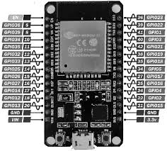
Pin Configuration and Descriptions
The ESP32 has multiple variants, but the following table outlines the general pin configuration for the ESP32-WROOM-32 module:
| Pin Name | Function | Description |
|---|---|---|
| GPIO0 | Input/Output, Boot Mode Selection | Used for boot mode selection during startup. |
| GPIO1 (TX0) | UART TX | UART0 transmit pin. |
| GPIO3 (RX0) | UART RX | UART0 receive pin. |
| GPIO2 | Input/Output | General-purpose I/O pin. |
| GPIO4 | Input/Output, PWM, ADC | Can be used for PWM or ADC functionality. |
| GPIO5 | Input/Output, PWM, SPI | Can be used for SPI or PWM functionality. |
| EN | Enable | Active-high enable pin. Resets the chip when pulled low. |
| 3V3 | Power Supply | 3.3V power input. |
| GND | Ground | Ground connection. |
| VIN | Power Supply | External power input (5V). |
Note: The ESP32 has many GPIO pins that are multiplexed with other functions. Refer to the datasheet for detailed pin assignments.
Usage Instructions
The ESP32 can be used in a variety of circuits and projects. Below are the steps and best practices for using the ESP32 effectively:
How to Use the ESP32 in a Circuit
Powering the ESP32:
- Use a regulated 3.3V power supply to power the ESP32 through the 3V3 pin.
- Alternatively, you can power the module via the VIN pin using a 5V source (e.g., USB).
Connecting to a Microcontroller or PC:
- Use a USB-to-serial adapter or a development board (e.g., ESP32 DevKit) to connect the ESP32 to your computer for programming.
- Install the necessary drivers (e.g., CP2102 or CH340) if required.
Programming the ESP32:
- Install the Arduino IDE or ESP-IDF (Espressif IoT Development Framework).
- Add the ESP32 board support package to the Arduino IDE via the Board Manager.
Connecting Peripherals:
- Use the GPIO pins to connect sensors, actuators, or other peripherals.
- Ensure that the voltage levels of connected devices are compatible with the ESP32 (3.3V logic).
Important Considerations and Best Practices
- Deep Sleep Mode: Use the deep sleep mode to minimize power consumption in battery-powered applications.
- Pull-up/Pull-down Resistors: Some GPIO pins require external pull-up or pull-down resistors for proper operation.
- Boot Mode: Ensure GPIO0 is pulled low during startup to enter programming mode.
- Voltage Levels: Avoid applying voltages higher than 3.3V to the GPIO pins to prevent damage.
Example Code for Arduino UNO Integration
The following example demonstrates how to use the ESP32 to connect to a Wi-Fi network and send data to a server:
#include <WiFi.h> // Include the WiFi library for ESP32

// Replace with your network credentials
const char* ssid = "Your_SSID";
const char* password = "Your_PASSWORD";

void setup() {
  Serial.begin(115200); // Initialize serial communication at 115200 baud
  delay(1000);

  // Connect to Wi-Fi
  Serial.println("Connecting to Wi-Fi...");
  WiFi.begin(ssid, password);

  while (WiFi.status() != WL_CONNECTED) {
    delay(500);
    Serial.print("."); // Print dots while connecting
  }

  Serial.println("\nWi-Fi connected!");
  Serial.print("IP Address: ");
  Serial.println(WiFi.localIP()); // Print the assigned IP address
}

void loop() {
  // Add your main code here
}
Note: Replace
Your_SSIDandYour_PASSWORDwith your Wi-Fi network credentials.
Troubleshooting and FAQs
Common Issues and Solutions
ESP32 Not Connecting to Wi-Fi:
- Double-check the SSID and password.
- Ensure the Wi-Fi network is operating on the 2.4 GHz band (ESP32 does not support 5 GHz).
Programming Errors:
- Ensure the correct board and port are selected in the Arduino IDE.
- Check that GPIO0 is pulled low during programming.
Random Resets or Instability:
- Verify that the power supply provides sufficient current (at least 500 mA).
- Add decoupling capacitors (e.g., 10 µF and 0.1 µF) near the power pins.
GPIO Pin Not Working:
- Check if the pin is being used for another function (e.g., ADC, SPI).
- Avoid using GPIO6-GPIO11 as they are reserved for flash memory.
FAQs
Q: Can the ESP32 operate on battery power?
A: Yes, the ESP32 can be powered by batteries. Use a voltage regulator or a LiPo battery with a 3.3V output.Q: How do I reset the ESP32?
A: Press the EN (Enable) button on the development board or pull the EN pin low momentarily.Q: Can the ESP32 be used as a standalone microcontroller?
A: Yes, the ESP32 is a complete SoC and can operate independently without an external microcontroller.Q: What is the maximum range of the ESP32's Wi-Fi?
A: The range depends on the environment but is typically up to 100 meters in open space.
This documentation provides a comprehensive guide to using the ESP32 effectively in your projects. For more advanced features, refer to the official Espressif documentation.