Cirkit Designer Logo
Cirkit Designer
Your all-in-one circuit design IDE
Home / 
Component Documentation

How to Use SMC01 stepper driver: Examples, Pinouts, and Specs

Image of SMC01 stepper driver
Cirkit Designer LogoDesign with SMC01 stepper driver in Cirkit Designer

Introduction

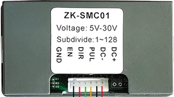
The SMC01 Stepper Driver is a device used to control the motion of stepper motors by sending precise electrical pulses to the motor windings. This allows for accurate positioning and speed control, making it an essential component in various applications such as CNC machines, 3D printers, robotics, and automated manufacturing systems.

Explore Projects Built with SMC01 stepper driver

Use Cirkit Designer to design, explore, and prototype these projects online. Some projects support real-time simulation. Click "Open Project" to start designing instantly!
Stepper Motor Control System with TB6600 Driver and DKC-1A Controller
Image of Copy of Copy of PLC-Based Step Motor Speed and Direction Control System: A project utilizing SMC01 stepper driver in a practical application
This circuit controls a bipolar stepper motor using a tb6600 micro stepping motor driver and a DKC-1A stepper motor controller. The system is powered by a 24VDC power supply and includes a relay module for additional control functionalities.
Cirkit Designer LogoOpen Project in Cirkit Designer
Stepper Motor Control System with SIMATIC S7-300 and TB6600 Driver
Image of Copy of PLC-Based Step Motor Speed and Direction Control System: A project utilizing SMC01 stepper driver in a practical application
This circuit controls a stepper motor using a tb6600 micro stepping motor driver and a DKC-1A stepper motor controller. The system is powered through panel mount banana sockets and includes a relay module for additional control, interfaced with a SIMATIC S7-300 PLC for automation.
Cirkit Designer LogoOpen Project in Cirkit Designer
Stepper Motor Control System with TB6600 Driver and Relay Integration
Image of Copy of Copy of Copy of PLC-Based Step Motor Speed and Direction Control System: A project utilizing SMC01 stepper driver in a practical application
This circuit controls a bipolar stepper motor using a tb6600 micro stepping motor driver and a DKC-1A stepper motor controller. It includes a 24VDC power supply, a 4-channel relay module, and panel mount banana sockets for power connections. The motor driver and controller are interconnected to manage the motor's direction and pulse signals.
Cirkit Designer LogoOpen Project in Cirkit Designer
CNC Machine Control System with Dual tb6600 Stepper Drivers and MAch3 USB Interface
Image of Jayshree CNC: A project utilizing SMC01 stepper driver in a practical application
This circuit appears to be a control system for a CNC machine or similar automated equipment. It includes two tb6600 Micro Stepping Motor Drivers for controlling stepper motors, a DC power source with a step-down buck converter to provide the necessary voltage levels, and a 4-channel relay module for switching higher power loads. The MAch3 CNC USB interface suggests the system is designed to interface with computer numerical control software, and the RMCS_3001 BLDC Driver indicates the presence of a brushless DC motor control. The Tiva C launchpad microcontroller and various connectors imply that the system is modular and may be programmable for specific automation tasks.
Cirkit Designer LogoOpen Project in Cirkit Designer

Explore Projects Built with SMC01 stepper driver

Use Cirkit Designer to design, explore, and prototype these projects online. Some projects support real-time simulation. Click "Open Project" to start designing instantly!
Image of Copy of Copy of PLC-Based Step Motor Speed and Direction Control System: A project utilizing SMC01 stepper driver in a practical application
Stepper Motor Control System with TB6600 Driver and DKC-1A Controller
This circuit controls a bipolar stepper motor using a tb6600 micro stepping motor driver and a DKC-1A stepper motor controller. The system is powered by a 24VDC power supply and includes a relay module for additional control functionalities.
Cirkit Designer LogoOpen Project in Cirkit Designer
Image of Copy of PLC-Based Step Motor Speed and Direction Control System: A project utilizing SMC01 stepper driver in a practical application
Stepper Motor Control System with SIMATIC S7-300 and TB6600 Driver
This circuit controls a stepper motor using a tb6600 micro stepping motor driver and a DKC-1A stepper motor controller. The system is powered through panel mount banana sockets and includes a relay module for additional control, interfaced with a SIMATIC S7-300 PLC for automation.
Cirkit Designer LogoOpen Project in Cirkit Designer
Image of Copy of Copy of Copy of PLC-Based Step Motor Speed and Direction Control System: A project utilizing SMC01 stepper driver in a practical application
Stepper Motor Control System with TB6600 Driver and Relay Integration
This circuit controls a bipolar stepper motor using a tb6600 micro stepping motor driver and a DKC-1A stepper motor controller. It includes a 24VDC power supply, a 4-channel relay module, and panel mount banana sockets for power connections. The motor driver and controller are interconnected to manage the motor's direction and pulse signals.
Cirkit Designer LogoOpen Project in Cirkit Designer
Image of Jayshree CNC: A project utilizing SMC01 stepper driver in a practical application
CNC Machine Control System with Dual tb6600 Stepper Drivers and MAch3 USB Interface
This circuit appears to be a control system for a CNC machine or similar automated equipment. It includes two tb6600 Micro Stepping Motor Drivers for controlling stepper motors, a DC power source with a step-down buck converter to provide the necessary voltage levels, and a 4-channel relay module for switching higher power loads. The MAch3 CNC USB interface suggests the system is designed to interface with computer numerical control software, and the RMCS_3001 BLDC Driver indicates the presence of a brushless DC motor control. The Tiva C launchpad microcontroller and various connectors imply that the system is modular and may be programmable for specific automation tasks.
Cirkit Designer LogoOpen Project in Cirkit Designer

Technical Specifications

Key Technical Details

Parameter Value
Supply Voltage 8V - 35V
Output Current 1.5A (max)
Microstepping Full, Half, 1/4, 1/8, 1/16
Control Interface Step and Direction
Logic Voltage 3.3V - 5V
Operating Temperature -20°C to 85°C

Pin Configuration and Descriptions

Pin Number Pin Name Description
1 GND Ground
2 VCC Power Supply (8V - 35V)
3 A+ Motor Coil A+
4 A- Motor Coil A-
5 B+ Motor Coil B+
6 B- Motor Coil B-
7 STEP Step Pulse Input
8 DIR Direction Control Input
9 EN Enable/Disable Input
10 MS1 Microstepping Resolution Select 1
11 MS2 Microstepping Resolution Select 2
12 MS3 Microstepping Resolution Select 3

Usage Instructions

How to Use the SMC01 Stepper Driver in a Circuit

  1. Power Supply Connection:

    • Connect the VCC pin to a power supply ranging from 8V to 35V.
    • Connect the GND pin to the ground of the power supply.
  2. Motor Connection:

    • Connect the stepper motor coils to the A+, A-, B+, and B- pins. Ensure correct pairing of the motor coils.
  3. Control Signal Connection:

    • Connect the STEP pin to a microcontroller or pulse generator to provide step pulses.
    • Connect the DIR pin to a microcontroller to control the direction of the motor.
    • Connect the EN pin to enable or disable the driver. Pulling this pin low will enable the driver.
  4. Microstepping Configuration:

    • Use the MS1, MS2, and MS3 pins to set the desired microstepping resolution. Refer to the table below for configuration:
MS1 MS2 MS3 Microstepping Mode
0 0 0 Full Step
1 0 0 Half Step
0 1 0 1/4 Step
1 1 0 1/8 Step
1 1 1 1/16 Step

Important Considerations and Best Practices

  • Ensure the power supply voltage is within the specified range to avoid damaging the driver.
  • Use appropriate heat sinks or cooling mechanisms if the driver operates at high currents for extended periods.
  • Double-check the motor coil connections to avoid incorrect wiring, which can damage the motor or driver.
  • Use decoupling capacitors close to the power supply pins to reduce noise and improve stability.

Example Code for Arduino UNO

// Define pin connections
const int stepPin = 3;  // Step pulse pin
const int dirPin = 4;   // Direction control pin
const int enPin = 5;    // Enable pin

void setup() {
  // Set pin modes
  pinMode(stepPin, OUTPUT);
  pinMode(dirPin, OUTPUT);
  pinMode(enPin, OUTPUT);

  // Enable the driver
  digitalWrite(enPin, LOW);

  // Set initial direction
  digitalWrite(dirPin, HIGH);
}

void loop() {
  // Generate step pulses
  for (int i = 0; i < 200; i++) {
    digitalWrite(stepPin, HIGH);
    delayMicroseconds(500);  // Adjust delay for speed control
    digitalWrite(stepPin, LOW);
    delayMicroseconds(500);
  }

  // Change direction
  digitalWrite(dirPin, !digitalRead(dirPin));
  delay(1000);  // Wait for a second before changing direction
}

Troubleshooting and FAQs

Common Issues and Solutions

  1. Motor Not Moving:

    • Solution: Check the power supply connections and ensure the voltage is within the specified range. Verify the motor coil connections and ensure the STEP and DIR signals are correctly connected.
  2. Driver Overheating:

    • Solution: Ensure proper cooling mechanisms are in place. Use heat sinks or cooling fans if necessary. Reduce the current limit if possible.
  3. Erratic Motor Movement:

    • Solution: Check for noise in the power supply and control signals. Use decoupling capacitors and shielded cables to reduce noise. Verify the microstepping configuration.

FAQs

  1. Can I use the SMC01 Stepper Driver with a 12V power supply?

    • Yes, the SMC01 Stepper Driver supports a power supply range of 8V to 35V, so a 12V power supply is suitable.
  2. How do I set the current limit for the stepper motor?

    • The SMC01 Stepper Driver does not have an adjustable current limit. Ensure the motor's rated current does not exceed the driver's maximum output current of 1.5A.
  3. Can I use the SMC01 Stepper Driver with a 3.3V logic microcontroller?

    • Yes, the SMC01 Stepper Driver supports logic voltages from 3.3V to 5V, making it compatible with both 3.3V and 5V microcontrollers.

By following this documentation, users can effectively integrate the SMC01 Stepper Driver into their projects, ensuring accurate and reliable control of stepper motors.