How to Use Battery UPS: Examples, Pinouts, and Specs
Introduction
A Battery Uninterruptible Power Supply (UPS) is an essential electronic component designed to provide backup power to devices during power outages or fluctuations. It ensures continuous operation of critical systems, protects sensitive electronics from damage, and prevents data loss. Battery UPS systems are commonly used in computers, networking equipment, medical devices, and industrial automation systems.
Explore Projects Built with Battery UPS


Explore Projects Built with Battery UPS
Common Applications and Use Cases:
- Backup power for personal computers and servers
- Protection for networking equipment such as routers and switches
- Powering medical devices during outages
- Ensuring uninterrupted operation of industrial control systems
- Supporting home automation and security systems
Technical Specifications
Below are the key technical details for a typical Battery UPS:
| Parameter | Value |
|---|---|
| Input Voltage Range | 100V - 240V AC |
| Output Voltage | 120V or 230V AC (depending on region) |
| Battery Type | Sealed Lead Acid (SLA) or Lithium-Ion |
| Battery Capacity | 7Ah to 100Ah (varies by model) |
| Backup Time | 5 minutes to several hours (load-dependent) |
| Output Waveform | Pure Sine Wave or Simulated Sine Wave |
| Transfer Time | < 10ms |
| Efficiency | Up to 95% |
| Operating Temperature | 0°C to 40°C |
| Communication Interface | USB, RS232, or Ethernet |
Pin Configuration and Descriptions
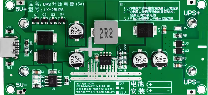
Battery UPS systems typically do not have pins like ICs or microcontrollers. However, they feature input/output connectors and communication ports. Below is a table describing these interfaces:
| Connector/Port | Description |
|---|---|
| AC Input Port | Connects to the main power supply (wall outlet) |
| AC Output Port(s) | Provides backup power to connected devices |
| Battery Terminals | Internal or external battery connection points |
| USB/RS232 Port | Allows communication with a computer for monitoring and configuration |
| Ethernet Port (optional) | Enables remote monitoring and management over a network |
Usage Instructions
How to Use the Battery UPS in a Circuit:
Setup and Installation:
- Place the UPS in a well-ventilated area, away from heat sources and moisture.
- Connect the UPS to a grounded AC power outlet using the provided power cable.
- Plug your electronic devices into the UPS's AC output ports.
Battery Connection:
- If the UPS uses an external battery, connect the battery terminals securely, ensuring correct polarity.
- For internal batteries, ensure they are properly installed and charged before use.
Power On:
- Turn on the UPS using the power button. The device will begin supplying power to connected devices.
- The UPS will automatically switch to battery mode during a power outage.
Monitoring and Configuration:
- Use the USB or RS232 port to connect the UPS to a computer.
- Install the manufacturer's monitoring software to view battery status, load levels, and event logs.
- Configure settings such as shutdown timers and alarms through the software interface.
Important Considerations and Best Practices:
- Load Capacity: Ensure the total power consumption of connected devices does not exceed the UPS's rated capacity.
- Battery Maintenance: Periodically check the battery health and replace it as recommended by the manufacturer.
- Ventilation: Keep the UPS in a location with adequate airflow to prevent overheating.
- Testing: Regularly test the UPS by simulating a power outage to ensure it functions correctly.
- Grounding: Always connect the UPS to a properly grounded outlet to avoid electrical hazards.
Arduino UNO Example:
While a Battery UPS is not directly connected to an Arduino, it can be used to power an Arduino-based project during outages. Below is an example of monitoring the UPS's battery status using an Arduino and a USB-to-serial adapter:
#include <SoftwareSerial.h>

// Define RX and TX pins for communication with the UPS
SoftwareSerial upsSerial(10, 11); // RX = pin 10, TX = pin 11

void setup() {
  Serial.begin(9600); // Initialize serial monitor
  upsSerial.begin(9600); // Initialize UPS communication

  Serial.println("UPS Monitoring Started");
}

void loop() {
  // Check if data is available from the UPS
  if (upsSerial.available()) {
    String upsData = upsSerial.readString(); // Read data from UPS
    Serial.println("UPS Data: " + upsData); // Print data to serial monitor
  }

  delay(1000); // Wait for 1 second before checking again
}
Note: The specific commands and data format for communicating with the UPS depend on the manufacturer's protocol. Refer to the UPS's user manual for details.
Troubleshooting and FAQs
Common Issues and Solutions:
UPS Does Not Turn On:
- Ensure the UPS is connected to a working power outlet.
- Check the battery connection and charge level.
- Verify the power button is pressed and held for the required duration.
Short Backup Time:
- The battery may be old or degraded. Replace the battery if necessary.
- Reduce the load by disconnecting non-essential devices.
Overload Alarm:
- Disconnect some devices to reduce the load on the UPS.
- Ensure the total power consumption does not exceed the UPS's rated capacity.
No Communication with Computer:
- Check the USB or RS232 cable connection.
- Install the correct drivers and monitoring software for the UPS.
FAQs:
Q: How long does the UPS battery last?
A: The battery lifespan depends on usage and maintenance but typically ranges from 3 to 5 years.Q: Can I connect a printer to the UPS?
A: It is not recommended to connect high-power devices like printers to a UPS, as they can quickly drain the battery.Q: What is the difference between pure sine wave and simulated sine wave output?
A: Pure sine wave output is ideal for sensitive electronics, while simulated sine wave is suitable for less critical devices.Q: How often should I test my UPS?
A: Perform a self-test or simulated power outage test at least once every 3 months.
By following this documentation, users can effectively utilize a Battery UPS to ensure uninterrupted power for their devices and systems.