Cirkit Designer Logo
Cirkit Designer
Your all-in-one circuit design IDE
Home / 
Component Documentation

How to Use Gx16 8 Pin round Connector: Examples, Pinouts, and Specs

Image of Gx16 8 Pin round Connector
Cirkit Designer LogoDesign with Gx16 8 Pin round Connector in Cirkit Designer

Introduction

The Gx16 8 Pin Round Connector is a robust and versatile circular metal connector that is widely used in electronic applications requiring a secure and reliable connection. With its 8 pins, it is capable of handling multiple signal connections simultaneously, making it ideal for audio, video, and data transmission. Common applications include aviation electronics, communication equipment, and industrial control systems.

Explore Projects Built with Gx16 8 Pin round Connector

Use Cirkit Designer to design, explore, and prototype these projects online. Some projects support real-time simulation. Click "Open Project" to start designing instantly!
5-Pin Connector Synchronization Circuit
Image of UMB_Cable: A project utilizing Gx16 8 Pin round Connector in a practical application
This circuit consists of four 5-pin connectors, where two of the connectors are fully interconnected pin-to-pin. The purpose of this setup could be to create a parallel connection between the two 5-pin connectors, possibly for signal distribution or redundancy.
Cirkit Designer LogoOpen Project in Cirkit Designer
Pushbutton-Controlled Interface with 40-Pin Connector and UBS Power Supply
Image of connect 4: A project utilizing Gx16 8 Pin round Connector in a practical application
This circuit consists of a 40-pin connector interfacing with four pushbuttons and a UBS power supply. The pushbuttons are used as inputs to the connector, which then relays the signals to other components or systems. The UBS power supply provides the necessary 24V power to the pushbuttons and the common ground for the circuit.
Cirkit Designer LogoOpen Project in Cirkit Designer
24V Pushbutton Control Interface with 40-Pin Connector
Image of 4 på rad: A project utilizing Gx16 8 Pin round Connector in a practical application
This circuit consists of a 24V power supply unit (PSU) connected to four pushbuttons. Each pushbutton is wired such that pressing it will send a 24V signal to a corresponding general-purpose input (GP In) on a 40-pin connector. The common return path for the pushbuttons is connected to the 0V of the PSU, which is also connected to the common (Com) for input pins on the 40-pin connector, completing the circuit for each button press.
Cirkit Designer LogoOpen Project in Cirkit Designer
FTDI to UART Adapter with J26 Connector
Image of J26 CLOSEUP: A project utilizing Gx16 8 Pin round Connector in a practical application
This circuit connects an FTDI USB-to-serial converter to a standard serial interface via a J26 connector. It facilitates serial communication by linking the ground, transmit, receive, data terminal ready, and request to send signals between the FTDI chip and the J26 connector.
Cirkit Designer LogoOpen Project in Cirkit Designer

Explore Projects Built with Gx16 8 Pin round Connector

Use Cirkit Designer to design, explore, and prototype these projects online. Some projects support real-time simulation. Click "Open Project" to start designing instantly!
Image of UMB_Cable: A project utilizing Gx16 8 Pin round Connector in a practical application
5-Pin Connector Synchronization Circuit
This circuit consists of four 5-pin connectors, where two of the connectors are fully interconnected pin-to-pin. The purpose of this setup could be to create a parallel connection between the two 5-pin connectors, possibly for signal distribution or redundancy.
Cirkit Designer LogoOpen Project in Cirkit Designer
Image of connect 4: A project utilizing Gx16 8 Pin round Connector in a practical application
Pushbutton-Controlled Interface with 40-Pin Connector and UBS Power Supply
This circuit consists of a 40-pin connector interfacing with four pushbuttons and a UBS power supply. The pushbuttons are used as inputs to the connector, which then relays the signals to other components or systems. The UBS power supply provides the necessary 24V power to the pushbuttons and the common ground for the circuit.
Cirkit Designer LogoOpen Project in Cirkit Designer
Image of 4 på rad: A project utilizing Gx16 8 Pin round Connector in a practical application
24V Pushbutton Control Interface with 40-Pin Connector
This circuit consists of a 24V power supply unit (PSU) connected to four pushbuttons. Each pushbutton is wired such that pressing it will send a 24V signal to a corresponding general-purpose input (GP In) on a 40-pin connector. The common return path for the pushbuttons is connected to the 0V of the PSU, which is also connected to the common (Com) for input pins on the 40-pin connector, completing the circuit for each button press.
Cirkit Designer LogoOpen Project in Cirkit Designer
Image of J26 CLOSEUP: A project utilizing Gx16 8 Pin round Connector in a practical application
FTDI to UART Adapter with J26 Connector
This circuit connects an FTDI USB-to-serial converter to a standard serial interface via a J26 connector. It facilitates serial communication by linking the ground, transmit, receive, data terminal ready, and request to send signals between the FTDI chip and the J26 connector.
Cirkit Designer LogoOpen Project in Cirkit Designer

Technical Specifications

General Characteristics

  • Shell Material: Zinc alloy with chrome plating
  • Insulator Material: Bakelite
  • Contact Material: Copper with silver plating
  • Rated Voltage: 250V
  • Rated Current: 5A per pin
  • Endurance: 500 mating cycles
  • Temperature Range: -50°C to +70°C
  • Cable Diameter Compatibility: 5mm - 10mm

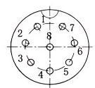
Pin Configuration and Descriptions

Pin Number Description
1 Signal 1
2 Signal 2
3 Signal 3
4 Signal 4
5 Signal 5
6 Signal 6
7 Signal 7
8 Signal 8

Note: The pin descriptions are generic and can be assigned specific functions based on the application.

Usage Instructions

Integration into a Circuit

  1. Cable Preparation: Strip the cable to expose the individual wires. Ensure that the cable diameter is compatible with the connector's specifications.
  2. Wire Soldering: Solder each wire to the corresponding pin on the connector. It is important to maintain a clean solder joint for each connection to ensure reliability.
  3. Assembly: Once all wires are soldered, assemble the backshell of the connector over the soldered pins and secure it in place.
  4. Testing: Before using the connector in a live circuit, test each connection with a multimeter to ensure there are no shorts or open circuits.

Best Practices

  • Use heat shrink tubing over each soldered connection to prevent shorts.
  • Ensure that the connector is properly oriented before mating to avoid damaging the pins.
  • Do not exceed the rated voltage and current specifications to prevent damage to the connector and connected devices.
  • Use a cable strain relief to prevent tension on the soldered connections.

Troubleshooting and FAQs

Common Issues and Solutions

  • Intermittent Connection: Check for cold solder joints or damaged pins. Re-solder if necessary.
  • Unable to Mate Connector: Ensure that the connector is properly aligned and that no foreign objects are obstructing the pins.
  • Excessive Resistance or Heat: Verify that the current through each pin does not exceed the rated 5A. Check for poor solder joints or damaged contacts.

FAQs

Q: Can the Gx16 8 Pin Connector be used for power applications? A: Yes, but ensure that the total current does not exceed the rated 5A per pin and the voltage does not exceed 250V.

Q: Is the connector waterproof? A: The Gx16 8 Pin Connector is not inherently waterproof. Additional sealing may be required for applications exposed to moisture.

Q: How do I prevent the connector from unscrewing during use? A: The connector features a threaded coupling that, when tightened, provides a secure connection. Use a thread locker if vibration is a concern.

Example Code for Arduino UNO

The following example demonstrates how to use the Gx16 8 Pin Connector with an Arduino UNO for a simple LED control circuit.

// Define the pin numbers connected to the LEDs
const int ledPins[] = {2, 3, 4, 5, 6, 7, 8, 9};

void setup() {
  // Set each pin as an output
  for (int i = 0; i < 8; i++) {
    pinMode(ledPins[i], OUTPUT);
  }
}

void loop() {
  // Turn on each LED in sequence
  for (int i = 0; i < 8; i++) {
    digitalWrite(ledPins[i], HIGH);
    delay(100);
    digitalWrite(ledPins[i], LOW);
  }
}

Note: This code assumes that each LED is connected to one of the pins on the Gx16 8 Pin Connector, with the other side of the LEDs connected to ground through a suitable current-limiting resistor.

Remember to keep your code comments concise and within the 80 character line length limit.