How to Use BNO055 9-axis abs. Orientation: Examples, Pinouts, and Specs
Introduction
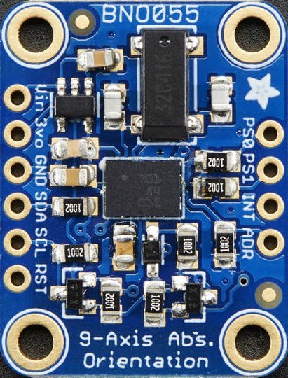
The BNO055 is a highly integrated sensor module manufactured by Adafruit (Part ID: BNO055). It combines a 3-axis accelerometer, 3-axis gyroscope, and 3-axis magnetometer to provide absolute orientation in 3D space. Unlike traditional sensors, the BNO055 features an onboard microcontroller that runs advanced sensor fusion algorithms, delivering accurate and stable orientation data without requiring external processing.
Explore Projects Built with BNO055 9-axis abs. Orientation


Explore Projects Built with BNO055 9-axis abs. Orientation
Common Applications
- Robotics and autonomous systems
- Drones and UAVs
- Augmented reality (AR) and virtual reality (VR) devices
- Motion tracking and gesture recognition
- Navigation systems
Technical Specifications
The following table outlines the key technical details of the BNO055 sensor:
| Parameter | Value |
|---|---|
| Operating Voltage | 3.3V to 5V |
| Communication Interfaces | I²C, UART |
| Power Consumption | ~12 mA (typical) |
| Accelerometer Range | ±2g, ±4g, ±8g, ±16g |
| Gyroscope Range | ±125°/s, ±250°/s, ±500°/s, ±2000°/s |
| Magnetometer Range | ±1300 µT |
| Operating Temperature | -40°C to +85°C |
| Dimensions | 5.2mm x 3.8mm x 1.1mm |
Pin Configuration and Descriptions
The BNO055 sensor module has the following pinout:
| Pin Name | Description |
|---|---|
| VIN | Power input (3.3V to 5V) |
| GND | Ground connection |
| SDA | I²C data line (connect to microcontroller's SDA pin) |
| SCL | I²C clock line (connect to microcontroller's SCL pin) |
| PS0 | Protocol selection pin (set to LOW for I²C, HIGH for UART) |
| PS1 | Protocol selection pin (set to LOW for I²C, HIGH for UART) |
| RST | Reset pin (active LOW, used to reset the sensor) |
| INT | Interrupt pin (used for event notifications, optional) |
Usage Instructions
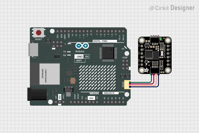
Connecting the BNO055 to an Arduino UNO
To use the BNO055 with an Arduino UNO, follow these steps:
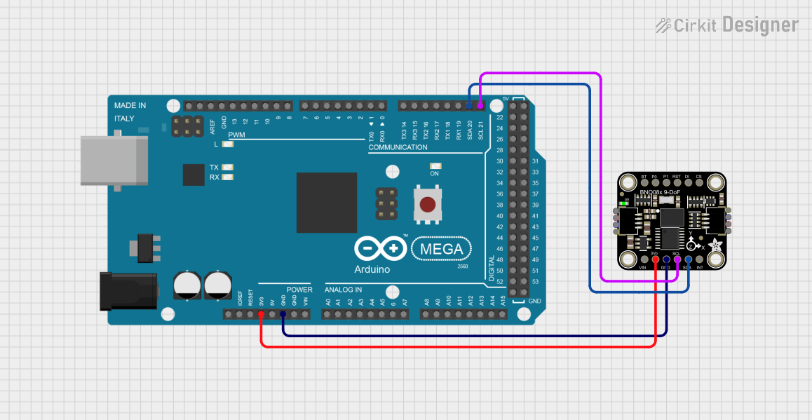
Wiring:
- Connect the VIN pin of the BNO055 to the 5V pin on the Arduino.
- Connect the GND pin of the BNO055 to the GND pin on the Arduino.
- Connect the SDA pin of the BNO055 to the A4 pin on the Arduino (I²C data line).
- Connect the SCL pin of the BNO055 to the A5 pin on the Arduino (I²C clock line).
- Ensure both PS0 and PS1 are set to LOW for I²C communication.
Install Required Libraries:
- Install the Adafruit BNO055 library from the Arduino Library Manager.
- Go to Sketch > Include Library > Manage Libraries, search for "Adafruit BNO055," and click Install.
Example Code: Use the following example code to read orientation data from the BNO055:
#include <Wire.h>
#include <Adafruit_Sensor.h>
#include <Adafruit_BNO055.h>

// Create an instance of the BNO055 sensor
Adafruit_BNO055 bno = Adafruit_BNO055(55);

void setup() {
  Serial.begin(9600);
  // Initialize the BNO055 sensor
  if (!bno.begin()) {
    Serial.println("Error: BNO055 not detected. Check wiring or I2C address.");
    while (1);
  }
  Serial.println("BNO055 initialized successfully!");
  bno.setExtCrystalUse(true); // Use external crystal for better accuracy
}

void loop() {
  // Get the sensor's orientation data
  sensors_event_t event;
  bno.getEvent(&event);

  // Print orientation data (roll, pitch, yaw)
  Serial.print("Orientation: ");
  Serial.print("X: "); Serial.print(event.orientation.x); Serial.print("° ");
  Serial.print("Y: "); Serial.print(event.orientation.y); Serial.print("° ");
  Serial.print("Z: "); Serial.print(event.orientation.z); Serial.println("°");

  delay(500); // Wait 500ms before the next reading
}
Important Considerations
- Power Supply: Ensure the sensor is powered with a stable voltage between 3.3V and 5V.
- I²C Pull-Up Resistors: If the I²C bus does not have pull-up resistors, add 4.7kΩ resistors between SDA/SCL and the power line.
- External Crystal: Enable the external crystal oscillator for improved accuracy in orientation measurements.
- Mounting Orientation: Mount the sensor securely and ensure it is aligned with the device's coordinate system for accurate readings.
Troubleshooting and FAQs
Common Issues
Sensor Not Detected:
- Cause: Incorrect wiring or I²C address mismatch.
- Solution: Double-check the connections and ensure the I²C address is set to 0x28 (default).
Inaccurate Orientation Data:
- Cause: Sensor not calibrated or external magnetic interference.
- Solution: Perform a full calibration (accelerometer, gyroscope, and magnetometer) and avoid placing the sensor near magnetic materials.
Random Resets or Instability:
- Cause: Insufficient power supply or noisy power source.
- Solution: Use a decoupling capacitor (e.g., 0.1µF) near the sensor's power pins.
FAQs
Q: Can the BNO055 be used with a Raspberry Pi?
A: Yes, the BNO055 can be connected to a Raspberry Pi using the I²C or UART interface. Use the Adafruit CircuitPython library for easy integration.
Q: How do I calibrate the BNO055?
A: The sensor provides calibration status for the accelerometer, gyroscope, and magnetometer. Move the sensor in all directions to achieve full calibration. Save the calibration data to avoid recalibration on every startup.
Q: What is the maximum I²C clock speed supported?
A: The BNO055 supports I²C clock speeds up to 400kHz (Fast Mode).
Q: Can I disable specific sensors (e.g., magnetometer)?
A: Yes, the BNO055 allows you to configure its operation mode to use only specific sensors (e.g., accelerometer + gyroscope).
By following this documentation, you can effectively integrate the BNO055 sensor into your projects and achieve accurate 3D orientation tracking.