Cirkit Designer Logo
Cirkit Designer
Your all-in-one circuit design IDE
Home / 
Component Documentation

How to Use Adafruit CYBERDECK Bonnet: Examples, Pinouts, and Specs

Image of Adafruit CYBERDECK Bonnet
Cirkit Designer LogoDesign with Adafruit CYBERDECK Bonnet in Cirkit Designer

Introduction

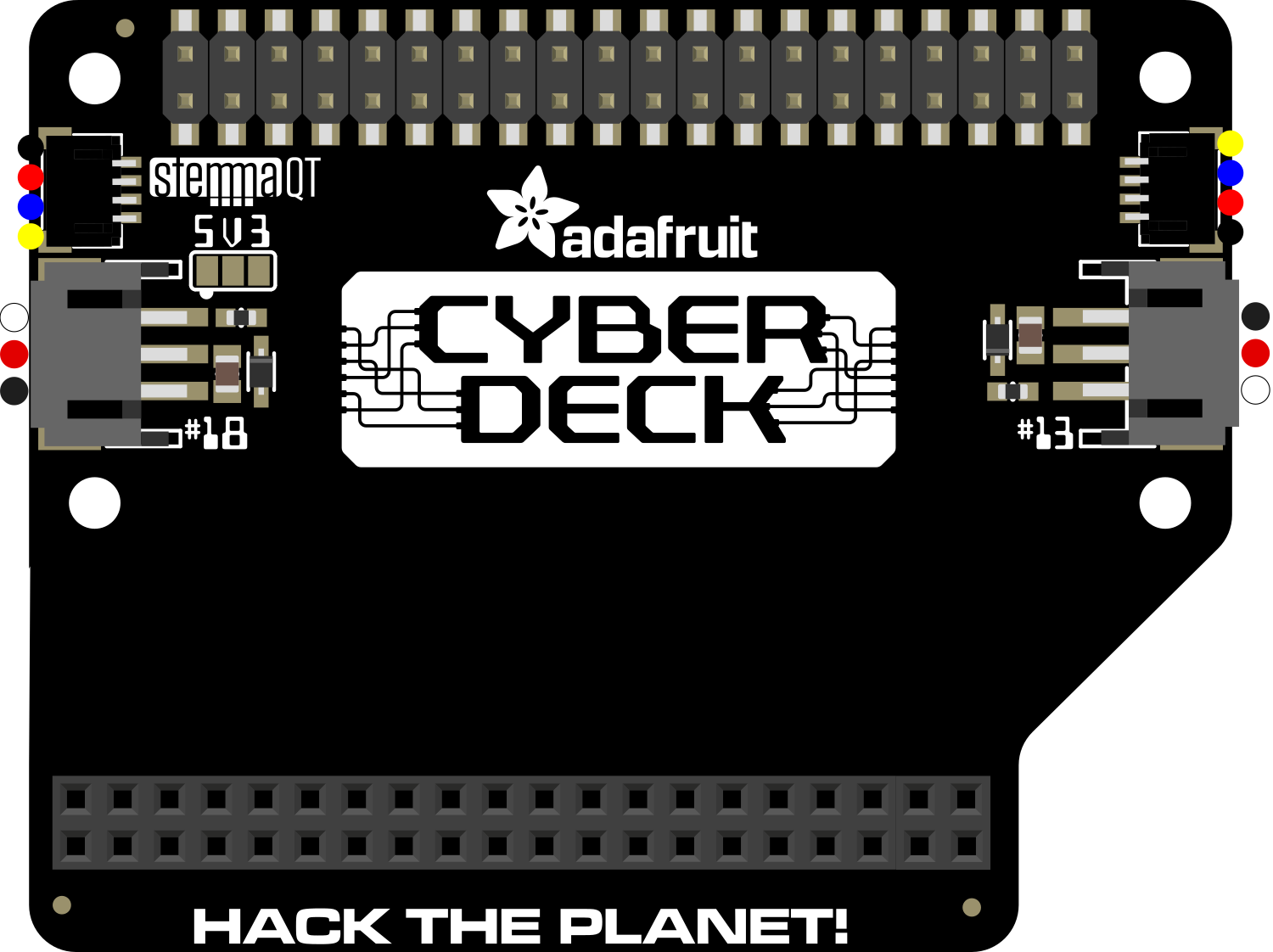
The Adafruit CYBERDECK Bonnet is an innovative and versatile add-on board designed for Raspberry Pi enthusiasts and cyberdeck builders. This compact board extends the capabilities of your Raspberry Pi by adding a full-color OLED display, user-interactive buttons, a NeoPixel LED, and additional GPIO access. It is ideal for creating portable computing projects, custom user interfaces, or adding visual and interactive elements to your creations.

Explore Projects Built with Adafruit CYBERDECK Bonnet

Use Cirkit Designer to design, explore, and prototype these projects online. Some projects support real-time simulation. Click "Open Project" to start designing instantly!
Raspberry Pi 4B-Based Multi-Sensor Interface Hub with GPS and GSM
Image of Rocket: A project utilizing Adafruit CYBERDECK Bonnet in a practical application
This circuit features a Raspberry Pi 4B interfaced with an IMX296 color global shutter camera, a Neo 6M GPS module, an Adafruit BMP388 barometric pressure sensor, an MPU-6050 accelerometer/gyroscope, and a Sim800l GSM module for cellular connectivity. Power management is handled by an MT3608 boost converter, which steps up the voltage from a Lipo battery, with a resettable fuse PTC and a 1N4007 diode for protection. The Adafruit Perma-Proto HAT is used for organizing connections and interfacing the sensors and modules with the Raspberry Pi via I2C and GPIO pins.
Cirkit Designer LogoOpen Project in Cirkit Designer
Raspberry Pi 4B-Based GPS and GSM Tracking System with Audio Feedback
Image of unlimited range: A project utilizing Adafruit CYBERDECK Bonnet in a practical application
This circuit features a Raspberry Pi 4B as the central processing unit, interfaced with a GPS NEO-6M V2 module for location tracking and an Adafruit FONA 808 Shield for cellular communication. It includes a PAM8406 5V Digital Audio Amplifier connected to an Adafruit STEMMA Speaker for audio output, and a Condenser Microphone connected to the FONA 808 for audio input. Power management is handled by a 12V battery connected to a voltage regulator that steps down the voltage to 5V and 3V required by the various components.
Cirkit Designer LogoOpen Project in Cirkit Designer
Battery-Powered Smart Sensor Hub with Adafruit QT Py RP2040
Image of wearable final: A project utilizing Adafruit CYBERDECK Bonnet in a practical application
This circuit features an Adafruit QT Py RP2040 microcontroller interfaced with an APDS9960 proximity sensor, an MPU6050 accelerometer and gyroscope, and an OLED display via I2C communication. It also includes a buzzer controlled by the microcontroller and is powered by a 3.7V LiPo battery with a toggle switch for power control.
Cirkit Designer LogoOpen Project in Cirkit Designer
Raspberry Pi 5 Smart Weather Station with GPS and AI Integration
Image of Senior Design: A project utilizing Adafruit CYBERDECK Bonnet in a practical application
This circuit integrates a Raspberry Pi 5 with various peripherals including an 8MP 3D stereo camera, an AI Hat, a BMP388 sensor, a 16x2 I2C LCD, and an Adafruit Ultimate GPS module. The Raspberry Pi serves as the central processing unit, interfacing with the camera for image capture, the AI Hat for AI processing, the BMP388 for environmental sensing, the LCD for display, and the GPS module for location tracking, with a USB Serial TTL for serial communication.
Cirkit Designer LogoOpen Project in Cirkit Designer

Explore Projects Built with Adafruit CYBERDECK Bonnet

Use Cirkit Designer to design, explore, and prototype these projects online. Some projects support real-time simulation. Click "Open Project" to start designing instantly!
Image of Rocket: A project utilizing Adafruit CYBERDECK Bonnet in a practical application
Raspberry Pi 4B-Based Multi-Sensor Interface Hub with GPS and GSM
This circuit features a Raspberry Pi 4B interfaced with an IMX296 color global shutter camera, a Neo 6M GPS module, an Adafruit BMP388 barometric pressure sensor, an MPU-6050 accelerometer/gyroscope, and a Sim800l GSM module for cellular connectivity. Power management is handled by an MT3608 boost converter, which steps up the voltage from a Lipo battery, with a resettable fuse PTC and a 1N4007 diode for protection. The Adafruit Perma-Proto HAT is used for organizing connections and interfacing the sensors and modules with the Raspberry Pi via I2C and GPIO pins.
Cirkit Designer LogoOpen Project in Cirkit Designer
Image of unlimited range: A project utilizing Adafruit CYBERDECK Bonnet in a practical application
Raspberry Pi 4B-Based GPS and GSM Tracking System with Audio Feedback
This circuit features a Raspberry Pi 4B as the central processing unit, interfaced with a GPS NEO-6M V2 module for location tracking and an Adafruit FONA 808 Shield for cellular communication. It includes a PAM8406 5V Digital Audio Amplifier connected to an Adafruit STEMMA Speaker for audio output, and a Condenser Microphone connected to the FONA 808 for audio input. Power management is handled by a 12V battery connected to a voltage regulator that steps down the voltage to 5V and 3V required by the various components.
Cirkit Designer LogoOpen Project in Cirkit Designer
Image of wearable final: A project utilizing Adafruit CYBERDECK Bonnet in a practical application
Battery-Powered Smart Sensor Hub with Adafruit QT Py RP2040
This circuit features an Adafruit QT Py RP2040 microcontroller interfaced with an APDS9960 proximity sensor, an MPU6050 accelerometer and gyroscope, and an OLED display via I2C communication. It also includes a buzzer controlled by the microcontroller and is powered by a 3.7V LiPo battery with a toggle switch for power control.
Cirkit Designer LogoOpen Project in Cirkit Designer
Image of Senior Design: A project utilizing Adafruit CYBERDECK Bonnet in a practical application
Raspberry Pi 5 Smart Weather Station with GPS and AI Integration
This circuit integrates a Raspberry Pi 5 with various peripherals including an 8MP 3D stereo camera, an AI Hat, a BMP388 sensor, a 16x2 I2C LCD, and an Adafruit Ultimate GPS module. The Raspberry Pi serves as the central processing unit, interfacing with the camera for image capture, the AI Hat for AI processing, the BMP388 for environmental sensing, the LCD for display, and the GPS module for location tracking, with a USB Serial TTL for serial communication.
Cirkit Designer LogoOpen Project in Cirkit Designer

Common Applications and Use Cases

  • Portable computing projects
  • Custom user interfaces for Raspberry Pi
  • DIY cyberdecks and gaming systems
  • Educational tools for learning electronics and programming
  • Interactive art installations

Technical Specifications

Key Technical Details

  • Voltage: 3.3V logic and power
  • Current: Depends on usage (OLED and NeoPixel draw additional current)
  • Power Ratings: 500mA max for the entire board
  • Display: 128x64 pixel OLED
  • Connectivity: I2C for OLED, GPIO for buttons and NeoPixel

Pin Configuration and Descriptions

Pin Number Description Notes
1 3.3V Power Power supply for the Bonnet
2 5V Power Not directly used by the Bonnet
3 SDA (I2C Data) OLED communication
4 5V Power Not directly used by the Bonnet
5 SCL (I2C Clock) OLED communication
6 Ground Common ground
... ... ...
12 GPIO18 (NeoPixel Data) NeoPixel control
... ... ...
36 GPIO16 (Button A) Button A input
37 GPIO26 (Button B) Button B input
... ... ...
40 GPIO21 (Button C) Button C input

Note: This table does not include all pins, only those relevant to the CYBERDECK Bonnet's features.

Usage Instructions

How to Use the Component in a Circuit

  1. Mounting the Bonnet: Carefully align the Bonnet's GPIO header with the Raspberry Pi's GPIO pins and press down to connect.
  2. Powering the Raspberry Pi: Ensure that your Raspberry Pi is powered through its standard USB power input.
  3. Software Setup: Install necessary libraries and drivers for the OLED display and NeoPixel LED. Adafruit provides detailed guides and software tools for this purpose.

Important Considerations and Best Practices

  • Power Requirements: Make sure your Raspberry Pi power supply can handle the additional current draw from the Bonnet.
  • I2C Addressing: The OLED display uses I2C communication. Ensure no I2C address conflicts with other peripherals.
  • GPIO Usage: Be aware of the GPIO pins used by the Bonnet to avoid conflicts with other connected components.
  • Static Electricity: Handle the Bonnet with care to avoid damage from electrostatic discharge.

Troubleshooting and FAQs

Common Issues Users Might Face

  • Display Not Working: Check I2C connections and ensure the OLED library is correctly installed.
  • Buttons Not Responsive: Verify the GPIO pins are correctly configured in your code.
  • NeoPixel Not Lighting Up: Ensure the NeoPixel GPIO pin is correctly defined and that the power supply is adequate.

Solutions and Tips for Troubleshooting

  • Recheck Wiring: Double-check all connections between the Raspberry Pi and the Bonnet.
  • Review Software Configuration: Make sure all software and libraries are up to date and properly configured.
  • Consult Documentation: Refer to the Adafruit guides for detailed setup and troubleshooting steps.

Example Code for Arduino UNO

While the Adafruit CYBERDECK Bonnet is designed for use with the Raspberry Pi, if you wish to interface it with an Arduino UNO, you can use the following example code to control the NeoPixel LED. Note that the OLED display and buttons require different libraries and setup for Arduino.

#include <Adafruit_NeoPixel.h>

#define PIN            6 // Define the pin connected to the NeoPixel data line
#define NUMPIXELS      1 // Number of NeoPixels

Adafruit_NeoPixel pixels(NUMPIXELS, PIN, NEO_GRB + NEO_KHZ800);

void setup() {
  pixels.begin(); // Initialize the NeoPixel library.
}

void loop() {
  pixels.setPixelColor(0, pixels.Color(255, 0, 0)); // Set the pixel to red
  pixels.show(); // Update the pixel color
  delay(500);
  
  pixels.setPixelColor(0, pixels.Color(0, 255, 0)); // Set the pixel to green
  pixels.show();
  delay(500);
  
  pixels.setPixelColor(0, pixels.Color(0, 0, 255)); // Set the pixel to blue
  pixels.show();
  delay(500);
}

Note: The above code is for illustrative purposes. The CYBERDECK Bonnet is not directly compatible with Arduino UNO without modifications.

For further assistance, Adafruit provides a community forum where you can ask questions and share your projects.