How to Use esp8266 nodemcu1.0: Examples, Pinouts, and Specs
Introduction
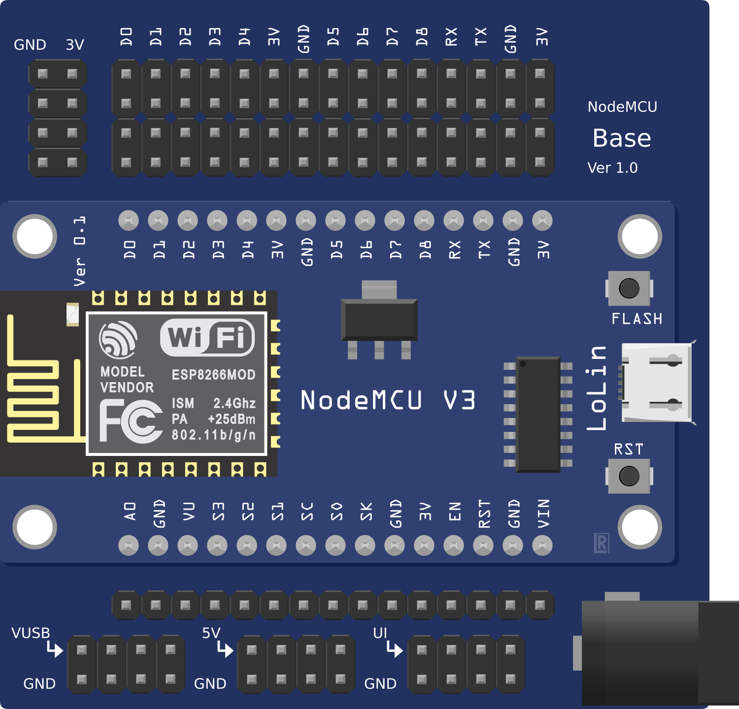
The ESP8266 NodeMCU 1.0 is a low-cost, open-source IoT platform based on the ESP8266 Wi-Fi module. It features a built-in microcontroller, GPIO pins, and support for various programming environments, such as Arduino IDE, Lua, and MicroPython. This versatile module is ideal for developing connected devices and IoT applications.
Explore Projects Built with esp8266 nodemcu1.0
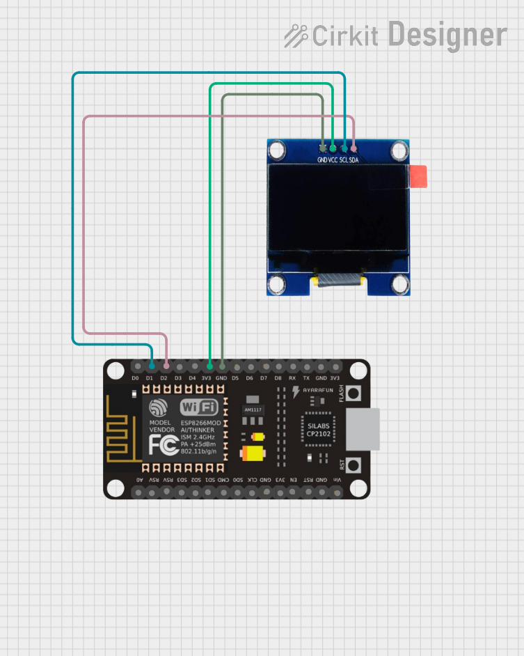
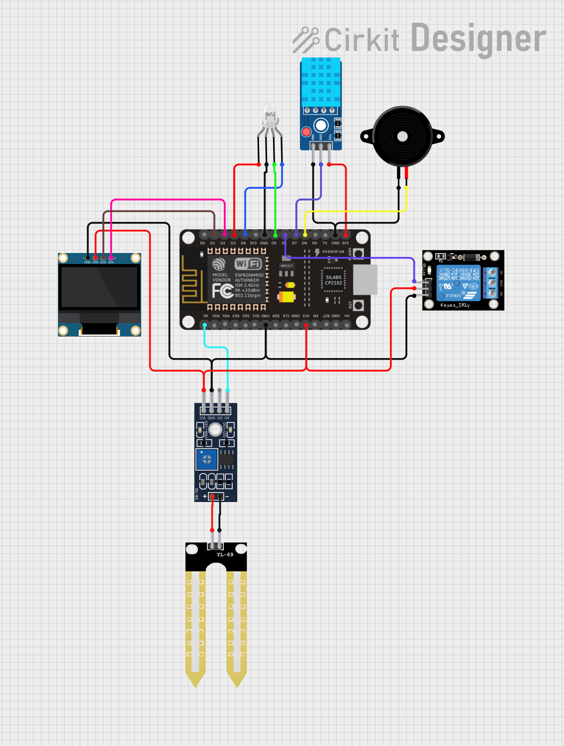

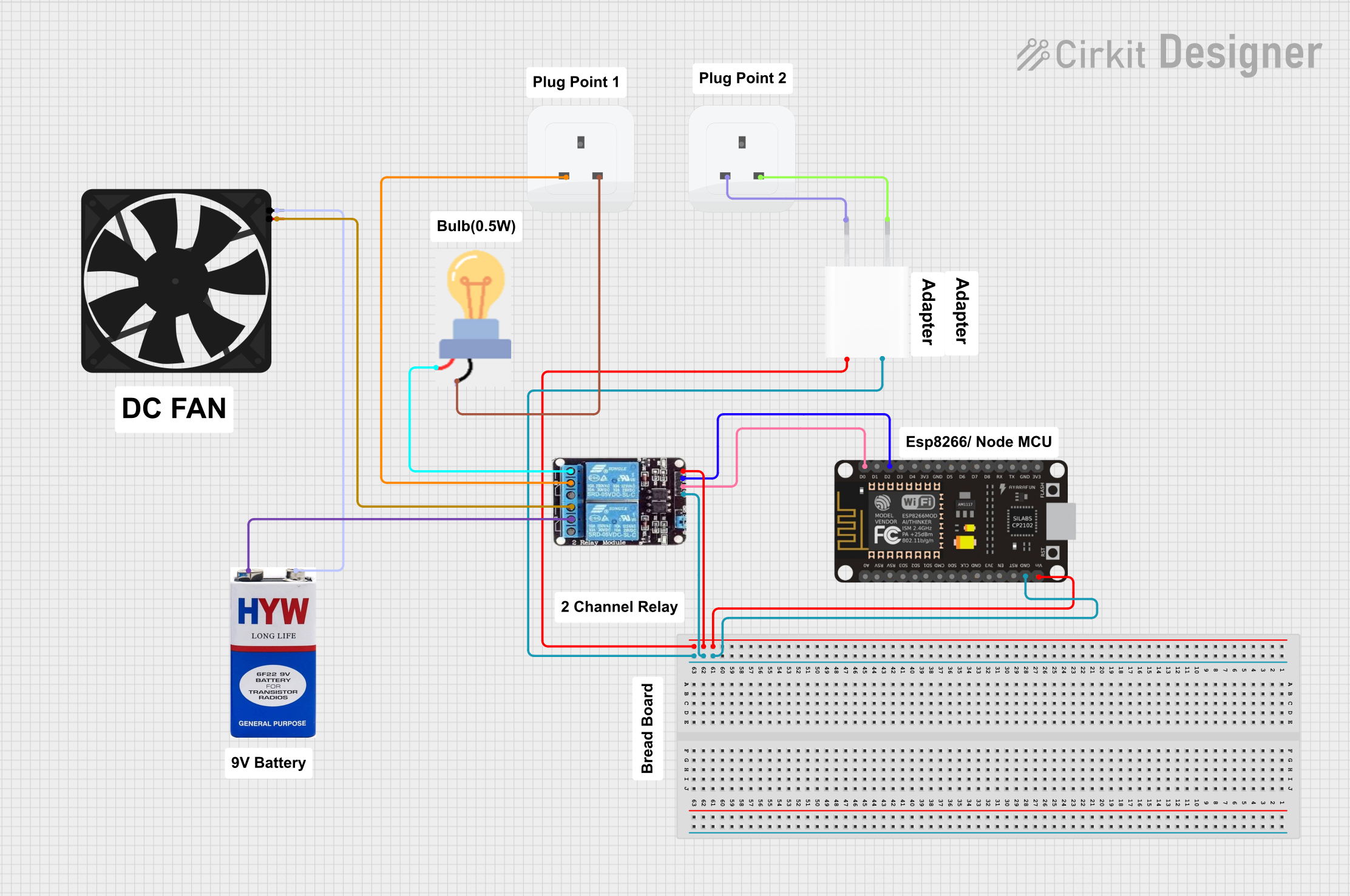
Explore Projects Built with esp8266 nodemcu1.0
Common Applications and Use Cases
- Home automation systems
- Smart appliances
- Wireless sensor networks
- IoT prototyping and development
- Remote monitoring and control systems
Technical Specifications
Key Technical Details
| Parameter | Value |
|---|---|
| Microcontroller | ESP8266 (Tensilica Xtensa LX106) |
| Operating Voltage | 3.3V |
| Input Voltage (VIN) | 4.5V - 10V |
| Digital I/O Pins | 11 |
| Analog Input Pins | 1 (10-bit ADC) |
| Flash Memory | 4MB (32Mbit) |
| Clock Speed | 80 MHz (up to 160 MHz) |
| Wi-Fi Standard | 802.11 b/g/n |
| Power Consumption | 15 µA (deep sleep), ~70 mA (Wi-Fi active) |
| Communication Protocols | UART, SPI, I2C |
| Dimensions | 49mm x 26mm x 13mm |
Pin Configuration and Descriptions
| Pin Name | Pin Number | Description |
|---|---|---|
| VIN | 1 | Power input (4.5V - 10V) |
| GND | 2 | Ground |
| 3V3 | 3 | 3.3V output for powering external components |
| D0 | 4 | GPIO16, can be used as a digital I/O pin |
| D1 | 5 | GPIO5, supports I2C (SCL) |
| D2 | 6 | GPIO4, supports I2C (SDA) |
| D3 | 7 | GPIO0, used for boot mode selection |
| D4 | 8 | GPIO2, onboard LED (active LOW) |
| D5 | 9 | GPIO14, supports SPI (SCLK) |
| D6 | 10 | GPIO12, supports SPI (MISO) |
| D7 | 11 | GPIO13, supports SPI (MOSI) |
| D8 | 12 | GPIO15, supports SPI (CS) |
| A0 | 13 | Analog input (0V - 3.3V, 10-bit resolution) |
| RX | 14 | UART RX (for serial communication) |
| TX | 15 | UART TX (for serial communication) |
| EN | 16 | Enable pin, active HIGH |
| RST | 17 | Reset pin, active LOW |
Usage Instructions
How to Use the ESP8266 NodeMCU 1.0 in a Circuit
Powering the Module:
- Connect the VIN pin to a 5V power source or use the micro-USB port for power.
- Ensure the GND pin is connected to the ground of your circuit.
Programming the Module:
- Install the Arduino IDE and add the ESP8266 board package via the Board Manager.
- Select "NodeMCU 1.0 (ESP-12E Module)" as the board in the Arduino IDE.
- Connect the module to your computer using a micro-USB cable.
Connecting Peripherals:
- Use the GPIO pins (D0-D8) to connect sensors, actuators, or other devices.
- For analog sensors, connect them to the A0 pin (ensure the voltage does not exceed 3.3V).
Uploading Code:
- Write your code in the Arduino IDE and upload it to the module.
- Ensure the correct COM port is selected in the IDE.
Example Code: Blinking the Onboard LED
// This example code blinks the onboard LED connected to GPIO2 (D4).

void setup() {
  pinMode(2, OUTPUT); // Set GPIO2 (D4) as an output pin
}

void loop() {
  digitalWrite(2, LOW);  // Turn the LED ON (active LOW)
  delay(1000);           // Wait for 1 second
  digitalWrite(2, HIGH); // Turn the LED OFF
  delay(1000);           // Wait for 1 second
}
Important Considerations and Best Practices
- Voltage Levels: Ensure all connected peripherals operate at 3.3V logic levels to avoid damaging the module.
- Power Supply: Use a stable power source to prevent unexpected resets or malfunctions.
- Wi-Fi Interference: Avoid placing the module near sources of electromagnetic interference for optimal Wi-Fi performance.
- Deep Sleep Mode: Use deep sleep mode to conserve power in battery-powered applications.
Troubleshooting and FAQs
Common Issues and Solutions
Issue: The module is not detected by the Arduino IDE.
Solution:- Ensure the correct drivers for the USB-to-serial chip (e.g., CH340 or CP2102) are installed.
- Check the USB cable for data transfer capability (some cables are power-only).
- Verify that the correct COM port is selected in the Arduino IDE.
Issue: The module keeps resetting or crashing.
Solution:- Check the power supply for stability and ensure it provides sufficient current (at least 500mA).
- Avoid connecting peripherals that draw excessive current directly from the module.
Issue: The Wi-Fi connection is unstable.
Solution:- Ensure the module is within range of the Wi-Fi router.
- Check for interference from other devices operating on the same frequency (2.4 GHz).
- Use a stronger antenna or external Wi-Fi module if necessary.
Issue: The analog input (A0) is not working correctly.
Solution:- Ensure the input voltage to A0 does not exceed 3.3V.
- Use a voltage divider if the sensor output exceeds the allowable range.
FAQs
Q1: Can I power the ESP8266 NodeMCU 1.0 with a 5V power supply?
A1: Yes, you can power the module via the VIN pin or the micro-USB port with a 5V supply. However, the GPIO pins operate at 3.3V logic levels.
Q2: How do I reset the module?
A2: You can reset the module by pressing the onboard reset button or pulling the RST pin LOW momentarily.
Q3: Can I use the ESP8266 NodeMCU 1.0 with MicroPython?
A3: Yes, the module supports MicroPython. You can flash the MicroPython firmware using tools like esptool.py and program it using a MicroPython IDE.
Q4: What is the maximum Wi-Fi range of the module?
A4: The Wi-Fi range depends on environmental factors but typically ranges from 30m to 50m indoors and up to 100m outdoors.