How to Use ESP32-DevKitM-1: Examples, Pinouts, and Specs
Introduction
The ESP32-DevKitM-1 is a compact development board based on the ESP32-MINI-1 module, which integrates the powerful ESP32 chip. This board is equipped with dual-mode Wi-Fi and Bluetooth capabilities, making it an excellent choice for Internet of Things (IoT) applications. Its small form factor and versatile GPIO pins allow developers to interface with a wide range of sensors, actuators, and other peripherals.
Explore Projects Built with ESP32-DevKitM-1


Explore Projects Built with ESP32-DevKitM-1
Common Applications and Use Cases
- Smart home devices (e.g., connected lights, thermostats)
- Wearable electronics
- Industrial IoT systems
- Wireless data logging and monitoring
- Prototyping Bluetooth Low Energy (BLE) and Wi-Fi-enabled devices
Technical Specifications
The ESP32-DevKitM-1 is designed to provide robust performance in a compact package. Below are its key technical details:
Key Technical Details
- Microcontroller: ESP32-MINI-1 module (based on ESP32 chip)
- Wireless Connectivity: Wi-Fi (802.11 b/g/n) and Bluetooth (v4.2 BR/EDR and BLE)
- Operating Voltage: 3.3V
- Input Voltage Range: 5V (via USB) or 3.3V (via external power supply)
- GPIO Pins: 15 (configurable for digital I/O, PWM, ADC, etc.)
- Flash Memory: 4 MB
- Operating Temperature: -40°C to 85°C
- Dimensions: 48.0 mm x 25.5 mm
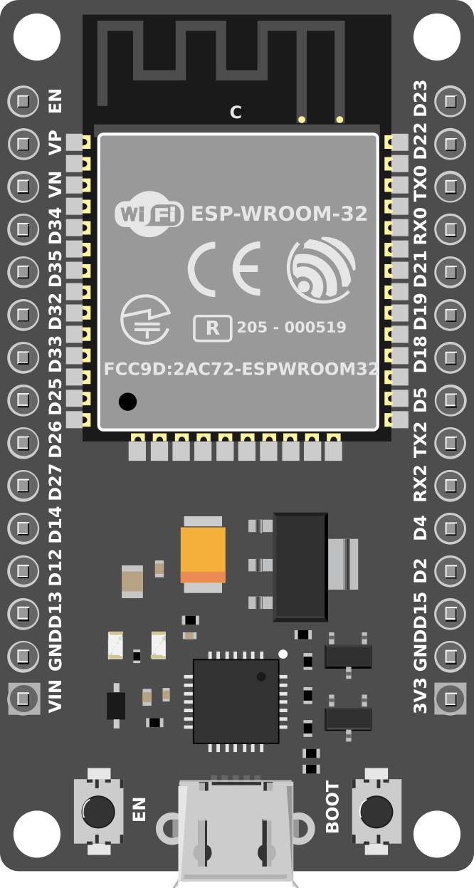
Pin Configuration and Descriptions
The ESP32-DevKitM-1 features a 16-pin layout. Below is the pinout and description:
| Pin | Name | Function |
|---|---|---|
| 1 | GND | Ground pin |
| 2 | 3V3 | 3.3V power output |
| 3 | EN | Enable pin (active high, used to reset the chip) |
| 4 | IO0 | GPIO0 (can also be used for boot mode selection) |
| 5 | IO1 | GPIO1 (UART TX by default) |
| 6 | IO3 | GPIO3 (UART RX by default) |
| 7 | IO4 | GPIO4 (configurable digital I/O) |
| 8 | IO5 | GPIO5 (configurable digital I/O) |
| 9 | IO12 | GPIO12 (configurable digital I/O, ADC, or touch input) |
| 10 | IO13 | GPIO13 (configurable digital I/O, ADC, or touch input) |
| 11 | IO14 | GPIO14 (configurable digital I/O, ADC, or touch input) |
| 12 | IO15 | GPIO15 (configurable digital I/O, ADC, or touch input) |
| 13 | IO16 | GPIO16 (configurable digital I/O) |
| 14 | IO17 | GPIO17 (configurable digital I/O) |
| 15 | GND | Ground pin |
| 16 | 5V | 5V power input (via USB or external power supply) |
Usage Instructions
The ESP32-DevKitM-1 is versatile and easy to use in a variety of projects. Below are the steps and best practices for using this development board.
How to Use the Component in a Circuit
Powering the Board:
- Connect the board to a computer or USB power source using a micro-USB cable.
- Alternatively, supply 3.3V directly to the 3V3 pin or 5V to the 5V pin.
Programming the Board:
- Install the Arduino IDE or ESP-IDF for development.
- Add the ESP32 board support package to the Arduino IDE via the Boards Manager.
- Select "ESP32 Dev Module" as the board type in the IDE.
Connecting Peripherals:
- Use the GPIO pins to connect sensors, actuators, or other devices.
- Ensure that the voltage levels of connected peripherals are compatible with the 3.3V logic of the ESP32.
Uploading Code:
- Write your code in the Arduino IDE or ESP-IDF.
- Connect the board to your computer via USB and select the correct COM port.
- Click the upload button to flash the code onto the ESP32.
Important Considerations and Best Practices
- Voltage Levels: Ensure that all connected peripherals operate at 3.3V logic levels to avoid damaging the board.
- Boot Mode: To enter bootloader mode, hold down the IO0 button while pressing the EN button.
- Power Supply: Use a stable power source to avoid unexpected resets or instability.
- Wi-Fi and Bluetooth: Avoid placing the board in metal enclosures, as this can interfere with wireless signals.
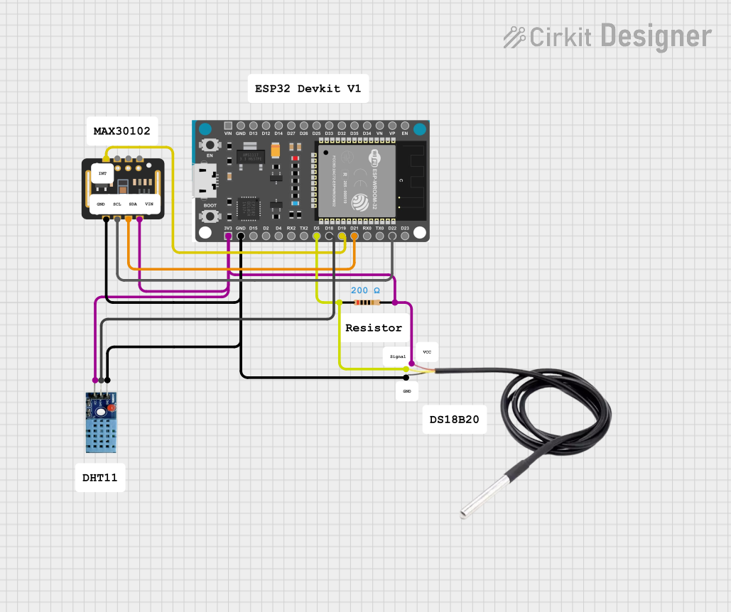
Example Code for Arduino UNO Integration
Below is an example of how to use the ESP32-DevKitM-1 to read data from a DHT11 temperature and humidity sensor and send it to a serial monitor:
#include <WiFi.h>
#include <DHT.h>

// Define the DHT sensor type and pin
#define DHTPIN 4       // GPIO4 is connected to the DHT sensor
#define DHTTYPE DHT11  // DHT11 sensor type

DHT dht(DHTPIN, DHTTYPE);

void setup() {
  Serial.begin(115200);  // Initialize serial communication
  dht.begin();           // Initialize the DHT sensor
  Serial.println("ESP32 DHT11 Example");
}

void loop() {
  delay(2000);  // Wait 2 seconds between readings

  // Read temperature and humidity values
  float humidity = dht.readHumidity();
  float temperature = dht.readTemperature();

  // Check if the readings are valid
  if (isnan(humidity) || isnan(temperature)) {
    Serial.println("Failed to read from DHT sensor!");
    return;
  }

  // Print the readings to the serial monitor
  Serial.print("Humidity: ");
  Serial.print(humidity);
  Serial.print("%  Temperature: ");
  Serial.print(temperature);
  Serial.println("°C");
}
Troubleshooting and FAQs
Common Issues Users Might Face
Board Not Detected by Computer:
- Ensure the USB cable is functional and supports data transfer.
- Install the correct USB-to-serial driver for the ESP32.
Code Upload Fails:
- Check that the correct COM port and board type are selected in the IDE.
- Hold down the IO0 button while pressing the EN button to enter bootloader mode.
Wi-Fi Connection Issues:
- Verify the SSID and password in your code.
- Ensure the router is within range and supports 2.4 GHz Wi-Fi.
Unstable Operation:
- Use a stable power source with sufficient current (at least 500 mA).
- Avoid connecting peripherals that draw excessive current.
Solutions and Tips for Troubleshooting
- Debugging: Use the Serial Monitor in the Arduino IDE to print debug messages.
- Resetting the Board: Press the EN button to reset the ESP32 if it becomes unresponsive.
- Firmware Updates: Update the ESP32 firmware using the ESP-IDF tools for improved stability and features.
By following this documentation, you can effectively use the ESP32-DevKitM-1 in your IoT and embedded systems projects.