How to Use ESP32S3 Zero: Examples, Pinouts, and Specs
Introduction
The ESP32S3 Zero is a low-power, dual-core microcontroller with integrated Wi-Fi and Bluetooth capabilities, designed specifically for Internet of Things (IoT) applications. It combines high performance with energy efficiency, making it ideal for battery-powered devices. The ESP32S3 Zero features a rich set of peripherals, including GPIO, ADC, SPI, I2C, and UART, enabling seamless integration into a wide range of embedded projects.
Explore Projects Built with ESP32S3 Zero


Explore Projects Built with ESP32S3 Zero
Common Applications and Use Cases
- Smart home devices (e.g., smart lights, thermostats)
- Wearable electronics
- Industrial IoT systems
- Wireless sensor networks
- Robotics and automation
- Real-time data monitoring and logging
Technical Specifications
Key Technical Details
- Processor: Dual-core Xtensa LX7, up to 240 MHz
- Memory: 512 KB SRAM, 384 KB ROM, and support for external PSRAM
- Wi-Fi: IEEE 802.11 b/g/n (2.4 GHz)
- Bluetooth: Bluetooth 5.0 (LE)
- Operating Voltage: 3.3V
- GPIO Pins: 45 (multiplexed with other functions)
- ADC: 12-bit, up to 20 channels
- Communication Interfaces: SPI, I2C, UART, I2S, CAN, and Ethernet MAC
- Power Consumption: Ultra-low power in deep sleep mode (~10 µA)
- Operating Temperature: -40°C to +85°C
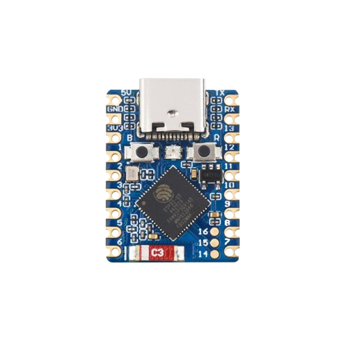
Pin Configuration and Descriptions
The ESP32S3 Zero has a total of 45 GPIO pins, many of which are multiplexed with other functions. Below is a table highlighting the key pins and their descriptions:
| Pin Name | Function | Description |
|---|---|---|
| GPIO0 | GPIO, Boot Mode Select | Used for boot mode selection during startup. |
| GPIO1 | UART TX | Default UART transmit pin. |
| GPIO3 | UART RX | Default UART receive pin. |
| GPIO12-19 | SPI Interface | SPI communication pins (MISO, MOSI, SCLK, CS). |
| GPIO21 | I2C SDA | Data line for I2C communication. |
| GPIO22 | I2C SCL | Clock line for I2C communication. |
| GPIO25-27 | ADC Channels | Analog input pins for ADC functionality. |
| GPIO32-39 | Touch Sensor Inputs | Capacitive touch sensing pins. |
| EN | Enable | Resets the chip when pulled low. |
| 3V3 | Power Supply | 3.3V power input. |
| GND | Ground | Ground connection. |
Note: Some GPIO pins are reserved for internal functions or are not recommended for general use. Refer to the ESP32S3 datasheet for detailed pin multiplexing information.
Usage Instructions
How to Use the ESP32S3 Zero in a Circuit
Powering the ESP32S3 Zero:
- Connect the 3.3V pin to a stable 3.3V power source.
- Ensure the GND pin is connected to the ground of the power supply.
Programming the ESP32S3 Zero:
- Use a USB-to-UART adapter to connect the ESP32S3 Zero to your computer.
- Install the ESP32 board package in the Arduino IDE or use the ESP-IDF framework for advanced development.
- Select the correct board and port in the IDE, then upload your code.
Connecting Peripherals:
- Use GPIO pins for digital input/output.
- Connect sensors or other analog devices to ADC pins (e.g., GPIO25-27).
- Use I2C (GPIO21, GPIO22) or SPI (GPIO12-19) for communication with external modules.
Important Considerations and Best Practices
- Voltage Levels: Ensure all connected peripherals operate at 3.3V logic levels to avoid damaging the ESP32S3 Zero.
- Deep Sleep Mode: Use deep sleep mode to minimize power consumption in battery-powered applications.
- Pull-up Resistors: For I2C communication, use appropriate pull-up resistors (typically 4.7kΩ) on the SDA and SCL lines.
- Boot Mode: To enter bootloader mode, hold GPIO0 low while resetting the device.
Example Code for Arduino UNO Integration
Below is an example of using the ESP32S3 Zero to read data from a DHT11 temperature and humidity sensor and send it to the Arduino Serial Monitor:
#include <DHT.h>

// Define the DHT sensor type and pin
#define DHTPIN 25  // Connect DHT data pin to GPIO25
#define DHTTYPE DHT11

DHT dht(DHTPIN, DHTTYPE);

void setup() {
  Serial.begin(115200);  // Initialize serial communication
  dht.begin();           // Initialize the DHT sensor
  Serial.println("ESP32S3 Zero - DHT11 Example");
}

void loop() {
  // Read temperature and humidity values
  float humidity = dht.readHumidity();
  float temperature = dht.readTemperature();

  // Check if the readings are valid
  if (isnan(humidity) || isnan(temperature)) {
    Serial.println("Failed to read from DHT sensor!");
    return;
  }

  // Print the readings to the Serial Monitor
  Serial.print("Humidity: ");
  Serial.print(humidity);
  Serial.print("%  Temperature: ");
  Serial.print(temperature);
  Serial.println("°C");

  delay(2000);  // Wait 2 seconds before the next reading
}
Note: Install the "DHT sensor library" in the Arduino IDE before uploading the code.
Troubleshooting and FAQs
Common Issues and Solutions
ESP32S3 Zero Not Detected by the Computer:
- Ensure the USB-to-UART driver is installed on your computer.
- Check the USB cable for damage or try a different cable.
Code Upload Fails:
- Verify that the correct board and port are selected in the Arduino IDE.
- Hold GPIO0 low and reset the device to enter bootloader mode.
Wi-Fi Connection Issues:
- Double-check the SSID and password in your code.
- Ensure the Wi-Fi network operates on the 2.4 GHz band (not 5 GHz).
High Power Consumption:
- Use deep sleep mode to reduce power usage.
- Disconnect unused peripherals to minimize current draw.
FAQs
Q: Can the ESP32S3 Zero operate at 5V?
A: No, the ESP32S3 Zero operates at 3.3V. Connecting 5V directly to its pins may damage the device.Q: How many devices can I connect via I2C?
A: The ESP32S3 Zero supports up to 127 devices on the I2C bus, depending on the address configuration.Q: Is the ESP32S3 Zero compatible with Arduino libraries?
A: Yes, the ESP32S3 Zero is compatible with most Arduino libraries, provided the ESP32 board package is installed.Q: Can I use the ESP32S3 Zero for audio processing?
A: Yes, the ESP32S3 Zero supports I2S for audio input/output and has sufficient processing power for basic audio applications.