Cirkit Designer Logo
Cirkit Designer
Your all-in-one circuit design IDE
Home / 
Component Documentation

How to Use Active Buzzer Module: Examples, Pinouts, and Specs

Image of Active Buzzer Module
Cirkit Designer LogoDesign with Active Buzzer Module in Cirkit Designer

Introduction

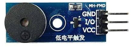
The Active Buzzer Module (RC-A-551) by Robocraze is an audio signaling device that is capable of generating a tone when powered. Unlike passive buzzers that require an AC signal to produce sound, active buzzers have an internal oscillating source and thus will generate sound with a DC voltage. This makes them particularly easy to use in various electronic projects, including alarms, timers, confirmation of user input, and other applications where audio feedback is required.

Explore Projects Built with Active Buzzer Module

Use Cirkit Designer to design, explore, and prototype these projects online. Some projects support real-time simulation. Click "Open Project" to start designing instantly!
Wi-Fi Controlled Buzzer with Wemos D1 Mini
Image of Buzzer Twinkle: A project utilizing Active Buzzer Module in a practical application
This circuit consists of a Wemos D1 Mini microcontroller connected to an active buzzer module. The Wemos D1 Mini provides power to the buzzer and controls it through its D1 pin, allowing for programmable sound output.
Cirkit Designer LogoOpen Project in Cirkit Designer
Voice-Controlled Buzzer System with VC-02 Module
Image of vc: A project utilizing Active Buzzer Module in a practical application
This circuit features a VC-02 voice recognition module connected to a buzzer and powered by a 5V battery. The VC-02 module is programmed to listen for specific voice commands and, upon recognizing the command 'can you make a sound', it activates the buzzer for one second. The circuit is designed for voice-activated sound generation, with the VC-02 module handling voice recognition and serial communication, and the buzzer providing audible feedback.
Cirkit Designer LogoOpen Project in Cirkit Designer
Battery-Powered PIR Motion Sensor Alarm with Relay and Buzzer
Image of motion detector using pir motio0n sensor: A project utilizing Active Buzzer Module in a practical application
This circuit is a motion-activated alarm system. It uses a PIR motion sensor to detect movement, which triggers a relay module to activate a buzzer powered by a 9V battery, providing an audible alert.
Cirkit Designer LogoOpen Project in Cirkit Designer
Arduino UNO Based Sensing Device with I2C LCD Feedback and Alert System
Image of 1st try: A project utilizing Active Buzzer Module in a practical application
This circuit uses an Arduino UNO to interface with an active buzzer, a green LED, and an I2C LCD display, possibly for user interaction and feedback. An INA125 instrumentation amplifier is connected to a copper coil for signal measurement and amplification. Power management is handled by a 9V battery with a rocker switch for on/off control.
Cirkit Designer LogoOpen Project in Cirkit Designer

Explore Projects Built with Active Buzzer Module

Use Cirkit Designer to design, explore, and prototype these projects online. Some projects support real-time simulation. Click "Open Project" to start designing instantly!
Image of Buzzer Twinkle: A project utilizing Active Buzzer Module in a practical application
Wi-Fi Controlled Buzzer with Wemos D1 Mini
This circuit consists of a Wemos D1 Mini microcontroller connected to an active buzzer module. The Wemos D1 Mini provides power to the buzzer and controls it through its D1 pin, allowing for programmable sound output.
Cirkit Designer LogoOpen Project in Cirkit Designer
Image of vc: A project utilizing Active Buzzer Module in a practical application
Voice-Controlled Buzzer System with VC-02 Module
This circuit features a VC-02 voice recognition module connected to a buzzer and powered by a 5V battery. The VC-02 module is programmed to listen for specific voice commands and, upon recognizing the command 'can you make a sound', it activates the buzzer for one second. The circuit is designed for voice-activated sound generation, with the VC-02 module handling voice recognition and serial communication, and the buzzer providing audible feedback.
Cirkit Designer LogoOpen Project in Cirkit Designer
Image of motion detector using pir motio0n sensor: A project utilizing Active Buzzer Module in a practical application
Battery-Powered PIR Motion Sensor Alarm with Relay and Buzzer
This circuit is a motion-activated alarm system. It uses a PIR motion sensor to detect movement, which triggers a relay module to activate a buzzer powered by a 9V battery, providing an audible alert.
Cirkit Designer LogoOpen Project in Cirkit Designer
Image of 1st try: A project utilizing Active Buzzer Module in a practical application
Arduino UNO Based Sensing Device with I2C LCD Feedback and Alert System
This circuit uses an Arduino UNO to interface with an active buzzer, a green LED, and an I2C LCD display, possibly for user interaction and feedback. An INA125 instrumentation amplifier is connected to a copper coil for signal measurement and amplification. Power management is handled by a 9V battery with a rocker switch for on/off control.
Cirkit Designer LogoOpen Project in Cirkit Designer

Technical Specifications

Key Technical Details

  • Operating Voltage: 3.3V to 5V
  • Rated Current: 30mA
  • Sound Output: ≥85dB
  • Resonant Frequency: 2300±300Hz
  • Operating Temperature: -20°C to 70°C

Pin Configuration and Descriptions

Pin Description
VCC Connects to the positive supply voltage (3.3V to 5V)
GND Connects to the ground of the power supply
I/O Input/output pin; when driven HIGH, the buzzer sounds
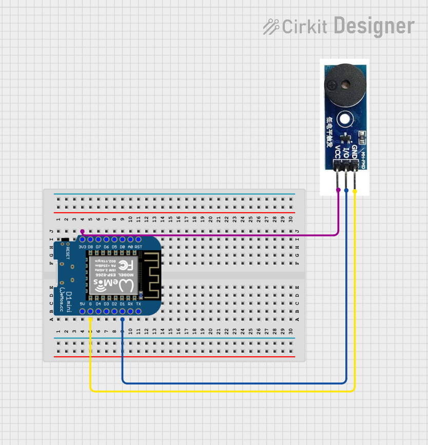
Usage Instructions

How to Use the Active Buzzer Module in a Circuit

  1. Power Connection: Connect the VCC pin to a 3.3V or 5V power supply and the GND pin to the ground.
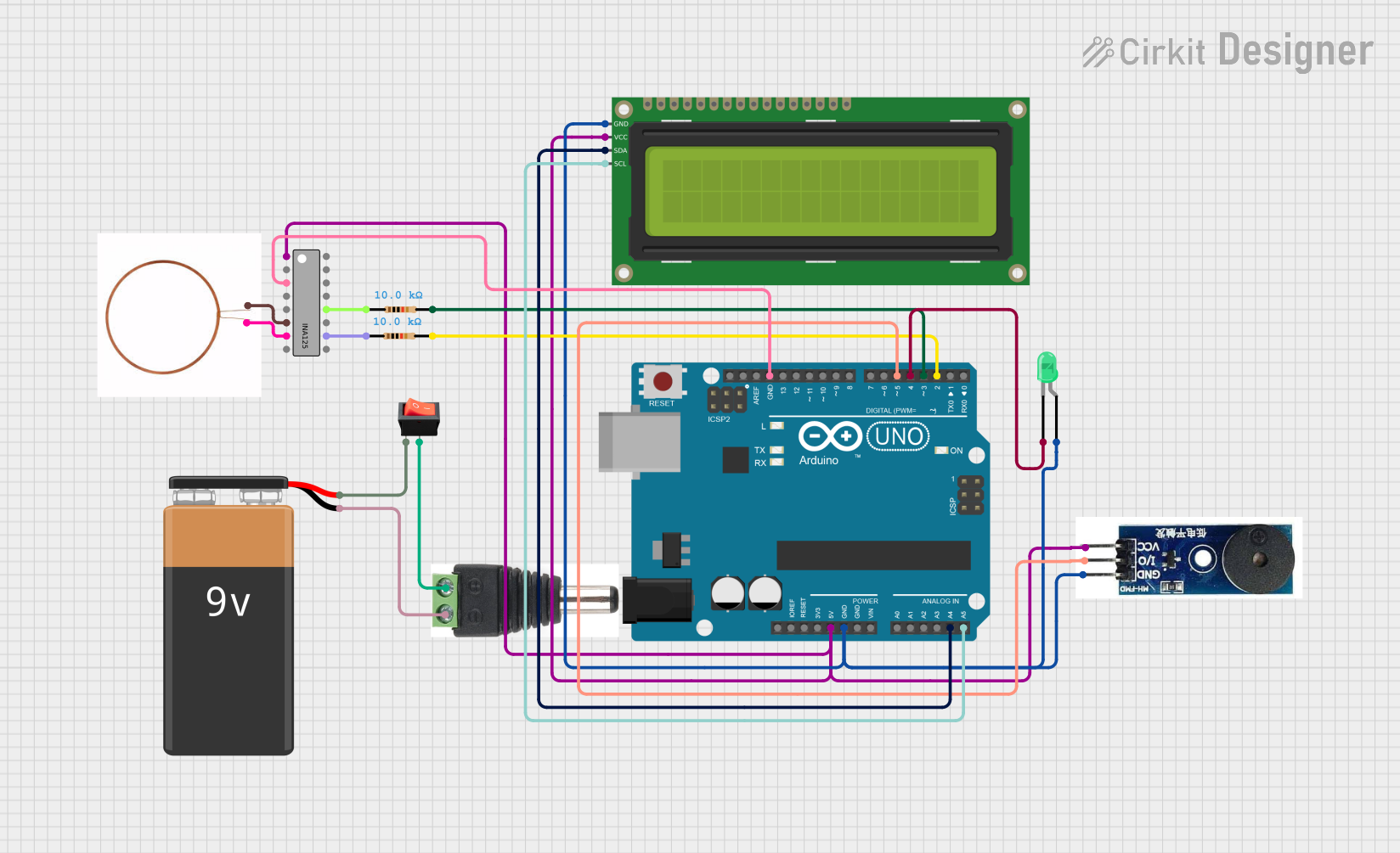
  2. Signal Input: Connect the I/O pin to a digital output pin on a microcontroller, such as an Arduino UNO.
  3. Activating the Buzzer: To activate the buzzer, set the digital output pin to HIGH. To deactivate, set it to LOW.

Important Considerations and Best Practices

  • Voltage Rating: Do not exceed the recommended operating voltage range (3.3V to 5V) to avoid damaging the buzzer.
  • Current Limitation: Ensure that the microcontroller's output pin can source the required current (30mA).
  • Pulse Control: For a more controlled sound, use pulse-width modulation (PWM) to create different tones.

Example Code for Arduino UNO

// Define the buzzer control pin
#define BUZZER_PIN 8

void setup() {
  // Set the buzzer pin as an output
  pinMode(BUZZER_PIN, OUTPUT);
}

void loop() {
  // Turn on the buzzer
  digitalWrite(BUZZER_PIN, HIGH);
  // Keep the buzzer on for 1 second
  delay(1000);
  // Turn off the buzzer
  digitalWrite(BUZZER_PIN, LOW);
  // Wait for 1 second before repeating the cycle
  delay(1000);
}

Troubleshooting and FAQs

Common Issues

  • Buzzer Does Not Sound: Ensure that the VCC and GND connections are correct and that the I/O pin is receiving a HIGH signal.
  • Low Sound Output: Verify that the operating voltage is within the specified range and that the buzzer is not being driven with a PWM signal at a low duty cycle.
  • Intermittent Sound: Check for loose connections or intermittent signals from the microcontroller.

Solutions and Tips for Troubleshooting

  • Check Connections: Double-check all wiring and solder joints for solid connections.
  • Test with a Multimeter: Use a multimeter to verify the voltage at the VCC pin and the signal at the I/O pin.
  • Replace the Buzzer: If the buzzer still does not work after checking connections and signals, consider replacing the component as it may be defective.

FAQs

Q: Can I use the active buzzer with a 9V battery? A: No, the active buzzer is designed to operate within a 3.3V to 5V range. Using a 9V battery can damage the component.

Q: How can I change the tone of the buzzer? A: The active buzzer produces a fixed tone due to its internal oscillator. To create different tones, you would need a passive buzzer and generate varying AC signals through the microcontroller.

Q: Is it possible to control the volume of the buzzer? A: The volume of the active buzzer is not directly controllable. However, you can indirectly affect the perceived volume by changing the distance or enclosure around the buzzer. For precise volume control, an external audio amplifier with volume adjustment would be required.

Q: Can I drive multiple buzzers with one microcontroller pin? A: Yes, as long as the combined current does not exceed the microcontroller pin's maximum current rating. It's recommended to use a transistor or a MOSFET as a switch if you need to drive multiple buzzers or if the buzzer's current exceeds the microcontroller's capability.