How to Use ESP-Prog: Examples, Pinouts, and Specs
Introduction
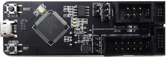
The ESP-Prog is a programming and debugging tool designed by Espressif for use with ESP32 and ESP8266 microcontrollers. It provides a convenient interface for flashing firmware and debugging applications, making it an essential tool for developers working with Espressif's microcontroller platforms. The ESP-Prog supports both JTAG debugging and UART communication, enabling efficient development and troubleshooting of embedded systems.
Explore Projects Built with ESP-Prog
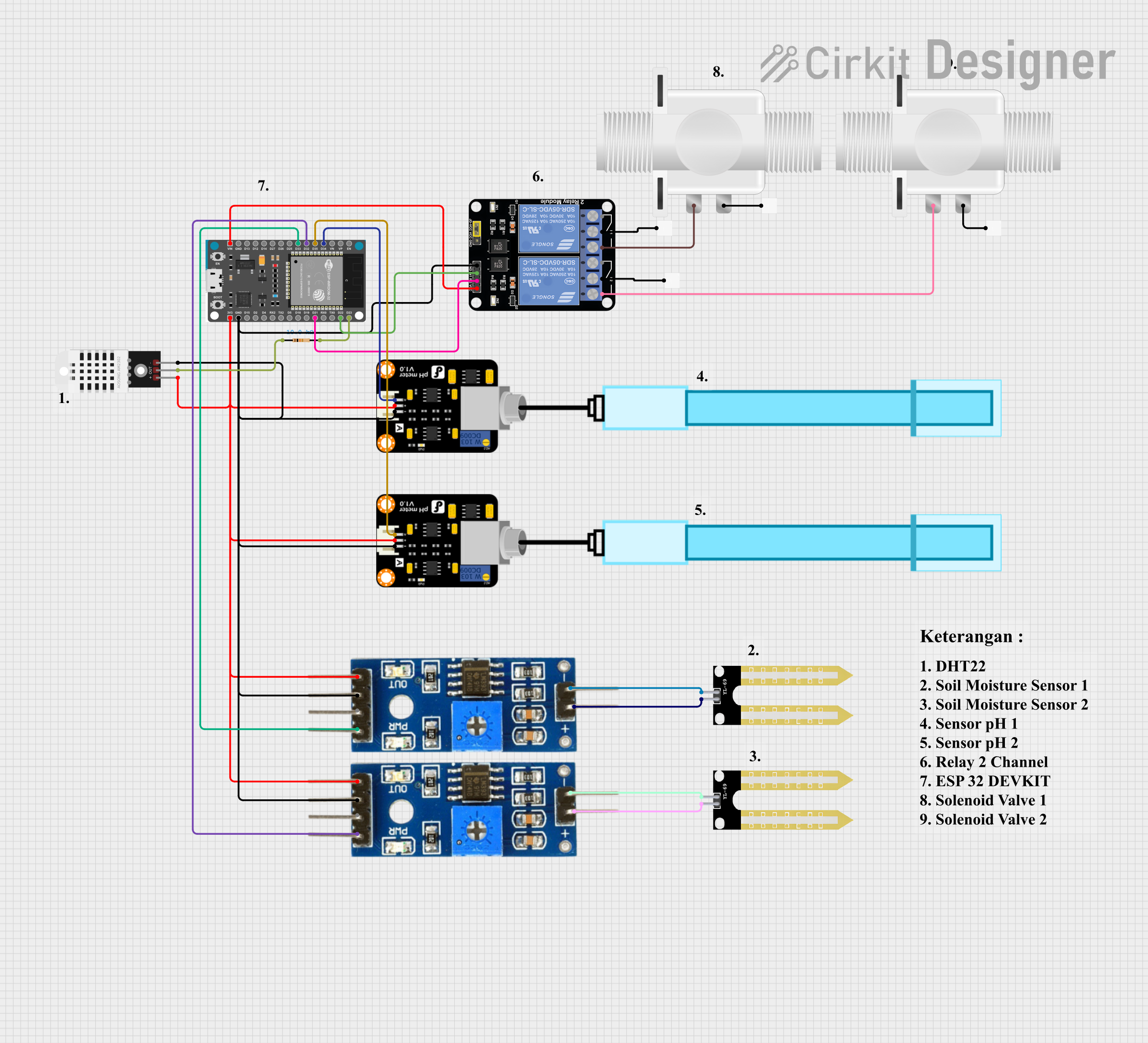


Explore Projects Built with ESP-Prog
Common Applications and Use Cases
- Flashing firmware onto ESP32 and ESP8266 microcontrollers.
- Debugging applications using JTAG.
- Serial communication with ESP32/ESP8266 for logging and monitoring.
- Development of IoT devices and embedded systems.
Technical Specifications
Key Technical Details
- Supported Microcontrollers: ESP32, ESP8266.
- Interfaces: JTAG, UART.
- Power Supply: USB-powered (5V).
- Connectivity: USB Type-C for host connection.
- Operating Systems: Compatible with Windows, macOS, and Linux.
- Dimensions: Compact and lightweight for portability.
Pin Configuration and Descriptions
The ESP-Prog has two main interfaces: the JTAG interface and the UART interface. Below is the pin configuration for each.
JTAG Interface Pinout
| Pin Number | Pin Name | Description |
|---|---|---|
| 1 | TCK | JTAG Clock |
| 2 | TDO | JTAG Data Out |
| 3 | TDI | JTAG Data In |
| 4 | TMS | JTAG Mode Select |
| 5 | GND | Ground |
| 6 | VCC | Power Supply (3.3V) for Target MCU |
UART Interface Pinout
| Pin Number | Pin Name | Description |
|---|---|---|
| 1 | TXD | UART Transmit Data |
| 2 | RXD | UART Receive Data |
| 3 | GND | Ground |
| 4 | VCC | Power Supply (3.3V) for Target MCU |
Usage Instructions
How to Use the ESP-Prog in a Circuit
Connect the ESP-Prog to the Host Computer:
- Use a USB Type-C cable to connect the ESP-Prog to your computer.
- Ensure the necessary drivers are installed (e.g., FTDI drivers for UART communication).
Connect the ESP-Prog to the Target Microcontroller:
- For JTAG debugging, connect the JTAG pins (TCK, TDO, TDI, TMS, GND, and VCC) to the corresponding pins on the ESP32/ESP8266.
- For UART communication, connect the TXD, RXD, GND, and VCC pins to the target microcontroller.
Flashing Firmware:
- Use Espressif's
esptool.pyor the ESP-IDF development environment to flash firmware onto the target microcontroller. - Example command for flashing firmware using
esptool.py:esptool.py --chip esp32 --port /dev/ttyUSB0 write_flash 0x1000 firmware.bin
- Use Espressif's
Debugging Applications:
- Use a compatible debugger (e.g., OpenOCD) to debug applications via the JTAG interface.
- Configure the debugger with the appropriate settings for the ESP32/ESP8266.
Important Considerations and Best Practices
- Ensure the target microcontroller is powered correctly (3.3V) to avoid damage.
- Use short and high-quality cables to minimize signal interference during debugging.
- When using the UART interface, ensure the baud rate is configured correctly in your software.
- For JTAG debugging, verify that the JTAG pins on the target microcontroller are not being used for other functions.
Example: Using ESP-Prog with Arduino UNO
While the ESP-Prog is not directly compatible with Arduino UNO, it can be used to program and debug ESP32/ESP8266 boards that are programmed using the Arduino IDE. Below is an example of flashing firmware to an ESP32 using the Arduino IDE:
- Install the ESP32 board package in the Arduino IDE.
- Connect the ESP-Prog to the ESP32 board via UART.
- Select the correct board and port in the Arduino IDE.
- Upload the sketch to the ESP32.
Example Arduino code for blinking an LED on an ESP32:
// This example code blinks an LED connected to GPIO2 on the ESP32.

void setup() {
  pinMode(2, OUTPUT); // Set GPIO2 as an output pin
}

void loop() {
  digitalWrite(2, HIGH); // Turn the LED on
  delay(1000);           // Wait for 1 second
  digitalWrite(2, LOW);  // Turn the LED off
  delay(1000);           // Wait for 1 second
}
Troubleshooting and FAQs
Common Issues and Solutions
ESP-Prog Not Detected by the Computer:
- Ensure the USB cable is functional and supports data transfer.
- Verify that the necessary drivers (e.g., FTDI drivers) are installed.
- Try connecting to a different USB port or computer.
Unable to Flash Firmware:
- Check the connections between the ESP-Prog and the target microcontroller.
- Ensure the correct port and chip type are specified in the flashing tool.
- Verify that the target microcontroller is in bootloader mode.
JTAG Debugging Not Working:
- Confirm that the JTAG pins on the target microcontroller are not being used for other functions.
- Check the debugger configuration and ensure it matches the target microcontroller.
UART Communication Issues:
- Verify the baud rate and other UART settings in your software.
- Check the TXD and RXD connections between the ESP-Prog and the target microcontroller.
FAQs
Q: Can the ESP-Prog power the target microcontroller?
A: Yes, the ESP-Prog can provide 3.3V power to the target microcontroller via the VCC pin. However, ensure the current requirements of the target do not exceed the ESP-Prog's capabilities.
Q: Is the ESP-Prog compatible with all ESP32/ESP8266 boards?
A: The ESP-Prog is compatible with most ESP32/ESP8266 boards that expose the necessary JTAG or UART pins.
Q: Can I use the ESP-Prog with other microcontrollers?
A: While the ESP-Prog is designed for ESP32/ESP8266, it may work with other microcontrollers that support JTAG or UART, but compatibility is not guaranteed.
Q: How do I update the ESP-Prog firmware?
A: The ESP-Prog does not require firmware updates as it acts as a bridge for programming and debugging. Ensure your development tools (e.g., ESP-IDF) are up to date for the latest features.