How to Use COB panel: Examples, Pinouts, and Specs
Introduction
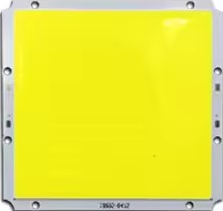
A Chip-on-Board (COB) panel is a cutting-edge LED lighting technology where multiple LED chips are mounted directly onto a substrate. This design allows for a compact form factor, efficient heat dissipation, and high luminous efficiency. COB panels are known for their ability to provide uniform light output and high brightness, making them ideal for a wide range of applications.
Explore Projects Built with COB panel

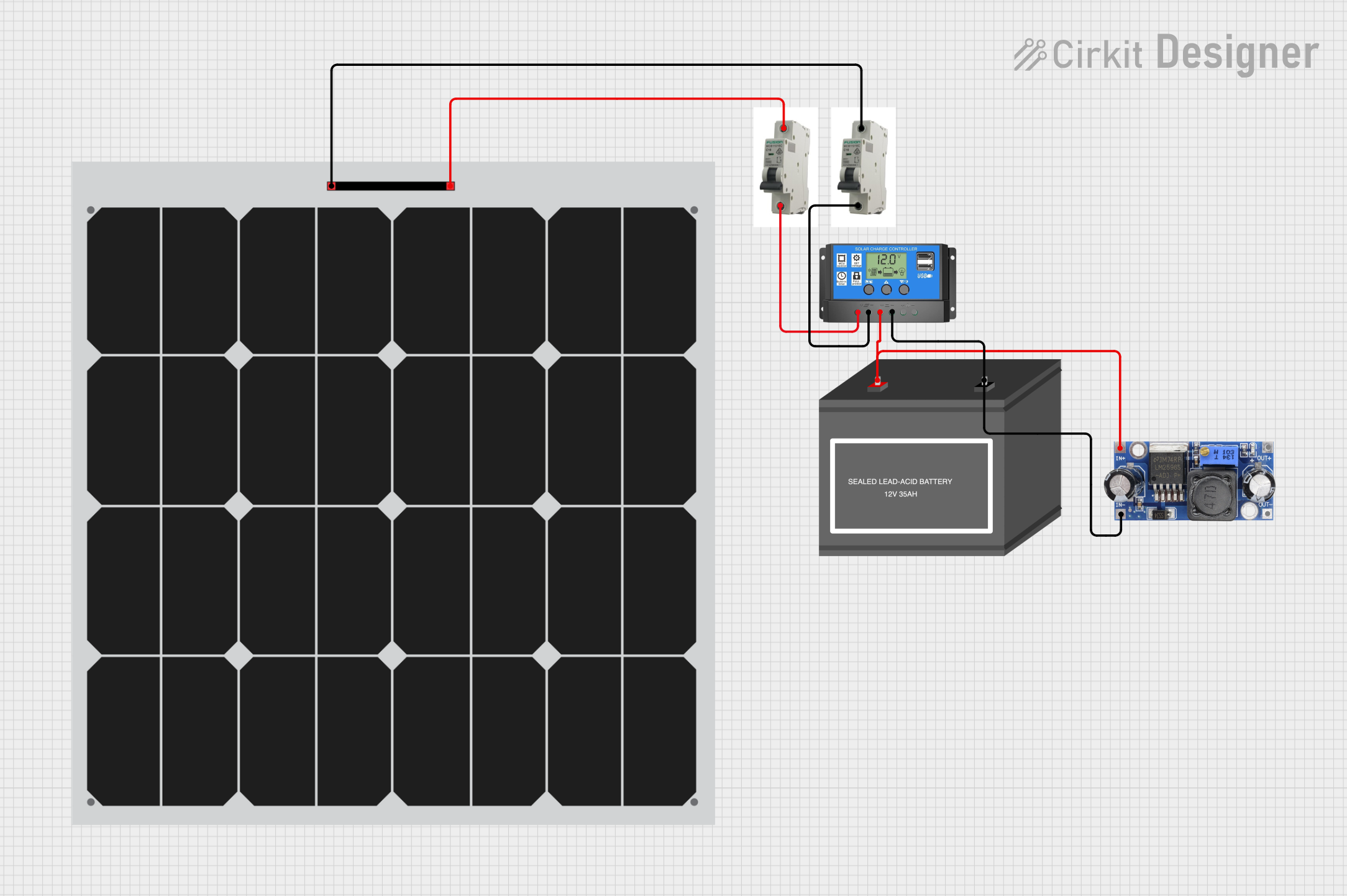
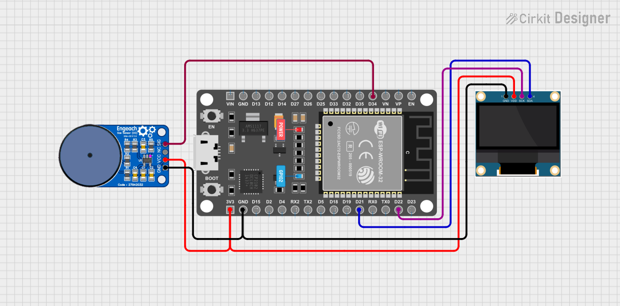

Explore Projects Built with COB panel
Common Applications and Use Cases
- General lighting (e.g., residential, commercial, and industrial lighting)
- Display backlighting
- Automotive lighting
- Photography and video lighting
- Flashlights and portable lighting devices
Technical Specifications
Below are the key technical details for a typical COB panel. Please refer to the specific datasheet for your model for exact values.
| Parameter | Value |
|---|---|
| Input Voltage | 12V DC or 24V DC (varies by model) |
| Power Consumption | 10W to 100W (depending on size) |
| Luminous Efficiency | 100-120 lm/W |
| Color Temperature | 2700K (warm white) to 6500K (cool white) |
| CRI (Color Rendering Index) | ≥80 |
| Operating Temperature | -20°C to 60°C |
| Lifespan | ≥30,000 hours |
Pin Configuration and Descriptions
COB panels typically have two main terminals for power input. Below is a general description:
| Pin | Label | Description |
|---|---|---|
| 1 | V+ | Positive terminal for DC input |
| 2 | V- | Negative terminal for DC input |
Note: Some COB panels may include additional pins for dimming or control. Refer to the specific datasheet for details.
Usage Instructions
How to Use the COB Panel in a Circuit
- Power Supply Selection: Ensure the power supply matches the voltage and current requirements of the COB panel. For example, a 12V DC COB panel requires a 12V DC power source.
- Heat Dissipation: Mount the COB panel onto a heat sink to prevent overheating. Use thermal paste or adhesive for better heat transfer.
- Wiring: Connect the V+ and V- terminals of the COB panel to the corresponding positive and negative terminals of the power supply.
- Optional Dimming: If the COB panel supports dimming, connect the dimming control pins to a compatible dimmer circuit or microcontroller.
Important Considerations and Best Practices
- Current Limiting: Use a constant current driver to prevent overdriving the LEDs, which can reduce their lifespan.
- Polarity: Double-check the polarity of the connections. Reversing the polarity can damage the COB panel.
- Ventilation: Ensure proper ventilation around the heat sink to maintain optimal operating temperatures.
- Avoid Direct Contact: Do not touch the LED surface directly, as oils from your skin can damage the LEDs.
Example: Connecting a COB Panel to an Arduino UNO
If your COB panel supports PWM dimming, you can control its brightness using an Arduino UNO. Below is an example code snippet:
// Example: PWM dimming control for a COB panel using Arduino UNO
// Connect the COB panel's dimming pin to Arduino pin 9 (PWM capable)

const int pwmPin = 9; // PWM pin connected to the COB panel dimming input

void setup() {
  pinMode(pwmPin, OUTPUT); // Set the pin as an output
}

void loop() {
  // Gradually increase brightness
  for (int brightness = 0; brightness <= 255; brightness++) {
    analogWrite(pwmPin, brightness); // Write PWM signal to dimming pin
    delay(10); // Small delay for smooth transition
  }

  // Gradually decrease brightness
  for (int brightness = 255; brightness >= 0; brightness--) {
    analogWrite(pwmPin, brightness); // Write PWM signal to dimming pin
    delay(10); // Small delay for smooth transition
  }
}
Note: Ensure the COB panel's dimming input is compatible with the Arduino's PWM signal (5V logic level). Use a transistor or MOSFET if higher current is required.
Troubleshooting and FAQs
Common Issues and Solutions
COB Panel Does Not Light Up
- Cause: Incorrect wiring or insufficient power supply.
- Solution: Verify the wiring and ensure the power supply meets the voltage and current requirements.
Flickering Light Output
- Cause: Unstable power supply or incompatible dimming signal.
- Solution: Use a stable constant current driver and ensure the dimming signal is within the specified range.
Overheating
- Cause: Inadequate heat dissipation.
- Solution: Attach the COB panel to a properly sized heat sink and ensure good ventilation.
Reduced Brightness Over Time
- Cause: Overdriving the LEDs or poor heat management.
- Solution: Use a constant current driver and ensure proper heat dissipation.
FAQs
Q: Can I power a COB panel directly from a battery?
A: Yes, as long as the battery voltage matches the COB panel's input voltage. Use a constant current driver for better performance and safety.
Q: How do I choose the right heat sink for my COB panel?
A: Select a heat sink with a thermal resistance low enough to keep the panel's operating temperature within the specified range. Larger panels typically require larger heat sinks.
Q: Can I use a COB panel outdoors?
A: Only if the COB panel is rated for outdoor use or enclosed in a weatherproof housing.
Q: What is the difference between COB and SMD LEDs?
A: COB LEDs have multiple chips mounted on a single substrate, providing uniform light output and better heat dissipation. SMD LEDs are individual chips mounted on a PCB, offering more flexibility in design but less uniformity in light output.