
Cirkit Designer Logo
Cirkit Designer
Your all-in-one circuit design IDE
Home / 
Component Documentation

How to Use SCP1000_D01: Examples, Pinouts, and Specs
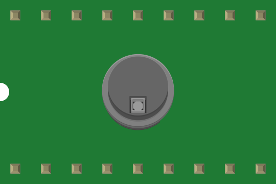

Image of SCP1000_D01
Cirkit Designer LogoDesign with SCP1000_D01 in Cirkit Designer

Introduction

The SCP1000_D01 is a high-precision environmental sensor designed to measure atmospheric pressure and temperature. It is widely used in applications such as weather monitoring, altimeters, and industrial automation systems. Its ability to provide accurate and reliable data makes it a popular choice for both hobbyists and professionals working on environmental monitoring projects.

Explore Projects Built with SCP1000_D01

Use Cirkit Designer to design, explore, and prototype these projects online. Some projects support real-time simulation. Click "Open Project" to start designing instantly!
Satellite-Based Timing and Navigation System with SDR and Atomic Clock Synchronization
Image of GPS 시스템 측정 구성도_Confirm: A project utilizing SCP1000_D01 in a practical application
This circuit appears to be a complex system involving power supply management, GPS and timing synchronization, and data communication. It includes a SI-TEX G1 Satellite Compass for GPS data, an XHTF1021 Atomic Rubidium Clock for precise timing, and Ettus USRP B200 units for software-defined radio communication. Power is supplied through various SMPS units and distributed via terminal blocks and DC jacks. Data communication is facilitated by Beelink MINI S12 N95 computers, RS232 splitters, and a 1000BASE-T Media Converter for network connectivity. RF Directional Couplers are used to interface antennas with the USRP units, and the entire system is likely contained within cases for protection and organization.
Cirkit Designer LogoOpen Project in Cirkit Designer
Battery-Powered Health Monitoring System with Nucleo WB55RG and OLED Display
Image of Pulsefex: A project utilizing SCP1000_D01 in a practical application
This circuit is a multi-sensor data acquisition system that uses a Nucleo WB55RG microcontroller to interface with a digital temperature sensor (TMP102), a pulse oximeter and heart-rate sensor (MAX30102), and a 0.96" OLED display via I2C. Additionally, it includes a Sim800l module for GSM communication, powered by a 3.7V LiPo battery.
Cirkit Designer LogoOpen Project in Cirkit Designer
Cellular-Enabled IoT Device with Real-Time Clock and Power Management
Image of LRCM PHASE 2 BASIC: A project utilizing SCP1000_D01 in a practical application
This circuit features a LilyGo-SIM7000G module for cellular communication and GPS functionality, interfaced with an RTC DS3231 for real-time clock capabilities. It includes voltage sensing through two voltage sensor modules, and uses an 8-channel opto-coupler for isolating different parts of the circuit. Power management is handled by a buck converter connected to a DC power source and batteries, with a fuse for protection and a rocker switch for on/off control. Additionally, there's an LED for indication purposes.
Cirkit Designer LogoOpen Project in Cirkit Designer
Arduino Mega 2560 Based Security System with Fingerprint Authentication and SMS Alerts
Image of Door security system: A project utilizing SCP1000_D01 in a practical application
This circuit features an Arduino Mega 2560 microcontroller interfaced with a SIM800L GSM module, two fingerprint scanners, an I2C LCD display, an IR sensor, and a piezo buzzer. Power management is handled by a PowerBoost 1000 Basic Pad USB, a TP4056 charging module, and a Li-ion 18650 battery, with an option to use a Mini AC-DC 110V-230V to 5V 700mA module for direct power supply. The primary functionality appears to be a security system with GSM communication capabilities, biometric access control, and visual/audible feedback.
Cirkit Designer LogoOpen Project in Cirkit Designer

Explore Projects Built with SCP1000_D01

Use Cirkit Designer to design, explore, and prototype these projects online. Some projects support real-time simulation. Click "Open Project" to start designing instantly!
Image of GPS 시스템 측정 구성도_Confirm: A project utilizing SCP1000_D01 in a practical application
Satellite-Based Timing and Navigation System with SDR and Atomic Clock Synchronization
This circuit appears to be a complex system involving power supply management, GPS and timing synchronization, and data communication. It includes a SI-TEX G1 Satellite Compass for GPS data, an XHTF1021 Atomic Rubidium Clock for precise timing, and Ettus USRP B200 units for software-defined radio communication. Power is supplied through various SMPS units and distributed via terminal blocks and DC jacks. Data communication is facilitated by Beelink MINI S12 N95 computers, RS232 splitters, and a 1000BASE-T Media Converter for network connectivity. RF Directional Couplers are used to interface antennas with the USRP units, and the entire system is likely contained within cases for protection and organization.
Cirkit Designer LogoOpen Project in Cirkit Designer
Image of Pulsefex: A project utilizing SCP1000_D01 in a practical application
Battery-Powered Health Monitoring System with Nucleo WB55RG and OLED Display
This circuit is a multi-sensor data acquisition system that uses a Nucleo WB55RG microcontroller to interface with a digital temperature sensor (TMP102), a pulse oximeter and heart-rate sensor (MAX30102), and a 0.96" OLED display via I2C. Additionally, it includes a Sim800l module for GSM communication, powered by a 3.7V LiPo battery.
Cirkit Designer LogoOpen Project in Cirkit Designer
Image of LRCM PHASE 2 BASIC: A project utilizing SCP1000_D01 in a practical application
Cellular-Enabled IoT Device with Real-Time Clock and Power Management
This circuit features a LilyGo-SIM7000G module for cellular communication and GPS functionality, interfaced with an RTC DS3231 for real-time clock capabilities. It includes voltage sensing through two voltage sensor modules, and uses an 8-channel opto-coupler for isolating different parts of the circuit. Power management is handled by a buck converter connected to a DC power source and batteries, with a fuse for protection and a rocker switch for on/off control. Additionally, there's an LED for indication purposes.
Cirkit Designer LogoOpen Project in Cirkit Designer
Image of Door security system: A project utilizing SCP1000_D01 in a practical application
Arduino Mega 2560 Based Security System with Fingerprint Authentication and SMS Alerts
This circuit features an Arduino Mega 2560 microcontroller interfaced with a SIM800L GSM module, two fingerprint scanners, an I2C LCD display, an IR sensor, and a piezo buzzer. Power management is handled by a PowerBoost 1000 Basic Pad USB, a TP4056 charging module, and a Li-ion 18650 battery, with an option to use a Mini AC-DC 110V-230V to 5V 700mA module for direct power supply. The primary functionality appears to be a security system with GSM communication capabilities, biometric access control, and visual/audible feedback.
Cirkit Designer LogoOpen Project in Cirkit Designer

Common Applications:

  • Weather stations
  • Altitude measurement in drones and aircraft
  • Industrial process monitoring
  • Environmental data logging systems
  • IoT-based automation projects

Technical Specifications

The SCP1000_D01 offers robust performance with the following key specifications:

Parameter Value
Operating Voltage 2.4V to 3.6V
Operating Current 3 µA (standby), 30 µA (active mode)
Pressure Range 30 kPa to 120 kPa
Temperature Range -20°C to +70°C
Pressure Resolution 1.5 Pa
Temperature Resolution 0.01°C
Communication Interface SPI

Pin Configuration and Descriptions

The SCP1000_D01 has an 8-pin configuration, as detailed below:

Pin Name Description
1 VDD Power supply (2.4V to 3.6V)
2 GND Ground connection
3 CSB Chip Select (active low)
4 MOSI Master Out Slave In (SPI data input)
5 MISO Master In Slave Out (SPI data output)
6 SCK Serial Clock (SPI clock input)
7 DRDY Data Ready (indicates new data is available)
8 NC Not Connected (leave unconnected or grounded)

Usage Instructions

How to Use the SCP1000_D01 in a Circuit

  1. Power Supply: Connect the VDD pin to a 3.3V power source and the GND pin to ground.
  2. SPI Communication: Connect the SPI pins (CSB, MOSI, MISO, SCK) to the corresponding SPI pins on your microcontroller.
  3. Data Ready Pin: Use the DRDY pin to detect when new data is available for reading.
  4. Pull-Up Resistors: Add pull-up resistors (10kΩ recommended) to the SPI lines if required by your microcontroller.
  5. Bypass Capacitor: Place a 0.1 µF capacitor between VDD and GND for noise filtering.

Best Practices:

  • Ensure the operating voltage does not exceed 3.6V to avoid damaging the sensor.
  • Use shielded cables for SPI connections in noisy environments.
  • Calibrate the sensor periodically for optimal accuracy.

Example Code for Arduino UNO

Below is an example of how to interface the SCP1000_D01 with an Arduino UNO using SPI:

#include <SPI.h>

// Define SCP1000 pins
#define CSB_PIN 10  // Chip Select pin
#define DRDY_PIN 9  // Data Ready pin

void setup() {
  // Initialize serial communication for debugging
  Serial.begin(9600);

  // Configure SPI settings
  SPI.begin();
  SPI.setDataMode(SPI_MODE0);  // SCP1000 uses SPI mode 0
  SPI.setClockDivider(SPI_CLOCK_DIV16);  // Set SPI clock speed
  pinMode(CSB_PIN, OUTPUT);
  pinMode(DRDY_PIN, INPUT);

  // Set CSB high to deselect the sensor
  digitalWrite(CSB_PIN, HIGH);

  Serial.println("SCP1000 initialized.");
}

void loop() {
  // Check if data is ready
  if (digitalRead(DRDY_PIN) == HIGH) {
    // Select the sensor
    digitalWrite(CSB_PIN, LOW);

    // Send command to read pressure data (example command: 0x1F)
    SPI.transfer(0x1F);
    delayMicroseconds(10);  // Wait for response

    // Read pressure data (16-bit value)
    uint8_t highByte = SPI.transfer(0x00);
    uint8_t lowByte = SPI.transfer(0x00);
    int pressure = (highByte << 8) | lowByte;

    // Deselect the sensor
    digitalWrite(CSB_PIN, HIGH);

    // Print pressure data
    Serial.print("Pressure: ");
    Serial.print(pressure);
    Serial.println(" Pa");
  }

  delay(1000);  // Wait 1 second before next reading
}

Notes:

  • Replace the 0x1F command with the appropriate command for your specific use case.
  • Ensure the SPI clock speed is compatible with the SCP1000_D01's requirements.

Troubleshooting and FAQs

Common Issues:

  1. No Data Output:

    • Ensure the CSB pin is correctly toggled (active low) during SPI communication.
    • Verify that the DRDY pin is being monitored for new data availability.
  2. Incorrect Readings:

    • Check the power supply voltage and ensure it is within the specified range.
    • Verify the SPI clock speed and mode settings.
  3. Sensor Not Responding:

    • Confirm all connections are secure and correctly wired.
    • Test the SPI communication with a logic analyzer to ensure proper data exchange.

FAQs:

Q: Can the SCP1000_D01 operate at 5V?
A: No, the SCP1000_D01 is designed to operate at a maximum voltage of 3.6V. Use a voltage regulator if your system operates at 5V.

Q: How do I calibrate the sensor?
A: Calibration involves comparing the sensor's output with a known reference and applying correction factors in your code. Refer to the manufacturer's datasheet for detailed calibration procedures.

Q: Can I use the SCP1000_D01 with I2C instead of SPI?
A: No, the SCP1000_D01 only supports SPI communication.

By following this documentation, you can effectively integrate the SCP1000_D01 into your projects and troubleshoot common issues with ease.

