How to Use mini560 pro: Examples, Pinouts, and Specs
Introduction
The Mini560 Pro is a compact, high-performance microcontroller development board designed for embedded applications. It is equipped with a powerful processor and a variety of connectivity options, including USB and GPIO pins, making it an ideal choice for prototyping and developing IoT devices. Its small form factor and versatile features make it suitable for a wide range of applications, such as home automation, wearable devices, robotics, and industrial control systems.
Common applications and use cases:
- IoT device prototyping
- Home automation systems
- Robotics and motor control
- Wearable technology
- Industrial monitoring and control
Explore Projects Built with mini560 pro

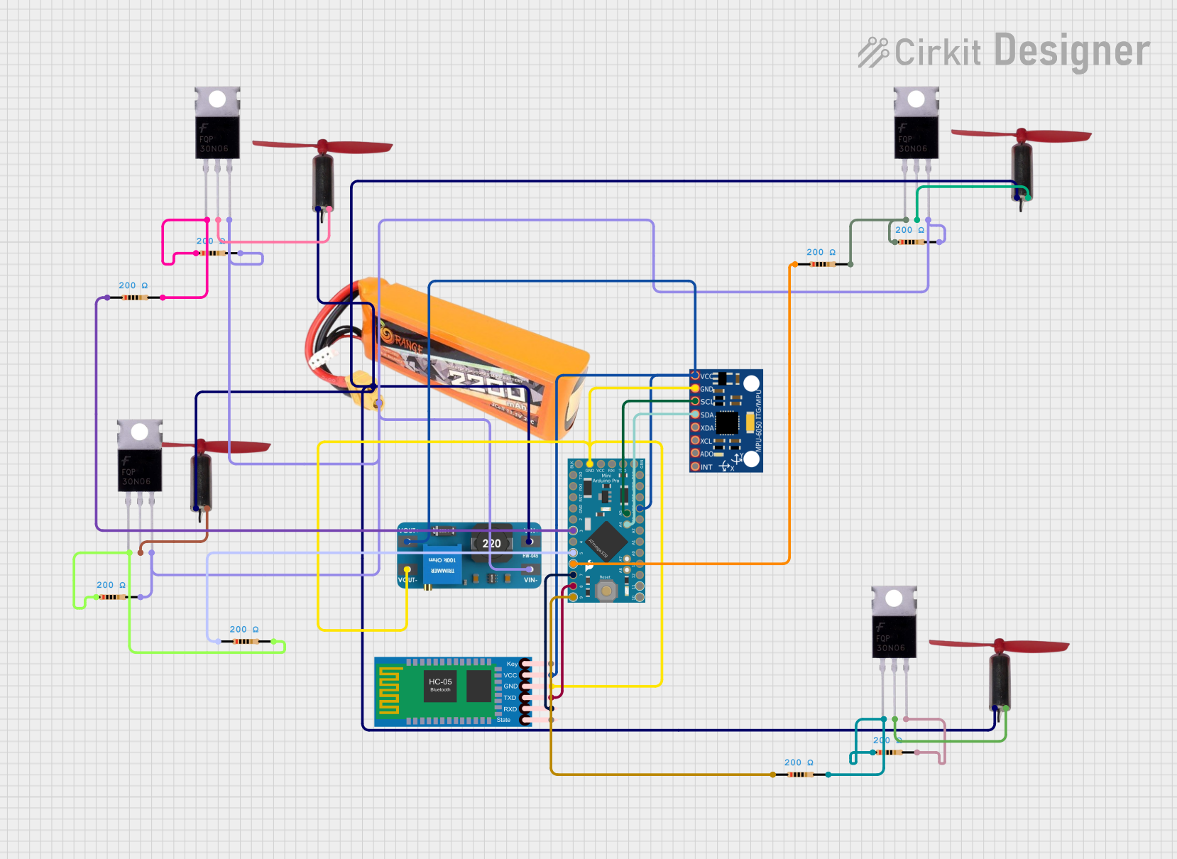
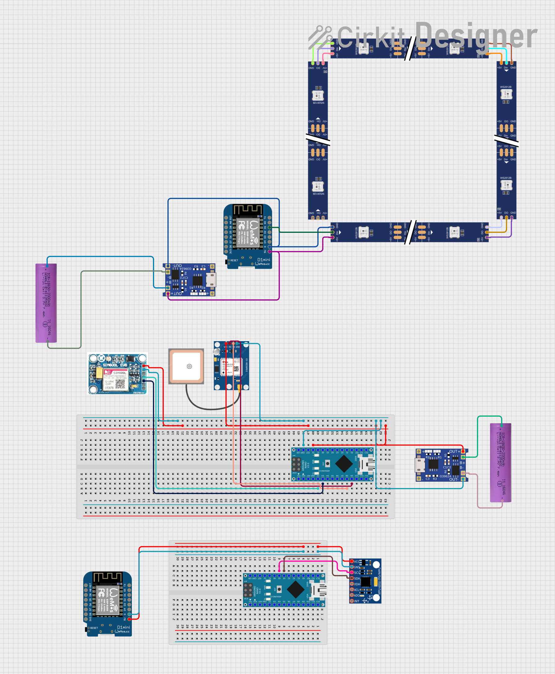

Explore Projects Built with mini560 pro
Technical Specifications
The Mini560 Pro offers robust performance and flexibility. Below are its key technical specifications:
General Specifications
| Parameter | Value |
|---|---|
| Microcontroller | ARM Cortex-M4 (32-bit) |
| Clock Speed | 120 MHz |
| Flash Memory | 512 KB |
| SRAM | 128 KB |
| Operating Voltage | 3.3V |
| Input Voltage (USB) | 5V |
| GPIO Pins | 20 |
| Communication Interfaces | UART, SPI, I2C, USB |
| Dimensions | 35mm x 25mm |
Pin Configuration and Descriptions
The Mini560 Pro features a total of 20 GPIO pins, which can be configured for various functions. Below is the pinout description:
| Pin Number | Label | Functionality |
|---|---|---|
| 1 | GND | Ground |
| 2 | 3.3V | Power output (3.3V) |
| 3 | D0 (RX) | UART Receive |
| 4 | D1 (TX) | UART Transmit |
| 5 | D2 | Digital I/O |
| 6 | D3 (PWM) | Digital I/O with PWM |
| 7 | D4 | Digital I/O |
| 8 | D5 (PWM) | Digital I/O with PWM |
| 9 | D6 (PWM) | Digital I/O with PWM |
| 10 | D7 | Digital I/O |
| 11 | D8 | Digital I/O |
| 12 | D9 (PWM) | Digital I/O with PWM |
| 13 | D10 (PWM) | Digital I/O with PWM |
| 14 | D11 (MOSI) | SPI Master Out Slave In |
| 15 | D12 (MISO) | SPI Master In Slave Out |
| 16 | D13 (SCK) | SPI Clock |
| 17 | A0 | Analog Input |
| 18 | A1 | Analog Input |
| 19 | A2 | Analog Input |
| 20 | A3 | Analog Input |
Usage Instructions
The Mini560 Pro is designed to be user-friendly and versatile. Follow these steps to use it in your project:
Connecting the Mini560 Pro
- Power Supply: Connect the Mini560 Pro to your computer or a USB power source using a micro-USB cable. The board operates at 3.3V internally but accepts 5V input via USB.
- GPIO Pins: Use the GPIO pins for digital and analog input/output. Refer to the pin configuration table for specific pin functions.
- Programming: The Mini560 Pro can be programmed using popular IDEs such as Arduino IDE or PlatformIO. Ensure the correct board and port are selected in the IDE.
Example: Blinking an LED with Arduino IDE
Below is an example of how to blink an LED connected to pin D3:
// Define the pin number for the LED
const int ledPin = 3; // D3 supports PWM

void setup() {
  // Set the LED pin as an output
  pinMode(ledPin, OUTPUT);
}

void loop() {
  // Turn the LED on
  digitalWrite(ledPin, HIGH);
  delay(1000); // Wait for 1 second

  // Turn the LED off
  digitalWrite(ledPin, LOW);
  delay(1000); // Wait for 1 second
}
Important Considerations
- Voltage Levels: Ensure that all connected peripherals operate at 3.3V logic levels to avoid damaging the board.
- Pin Current Limits: Each GPIO pin can source or sink a maximum of 20mA. Exceeding this limit may damage the board.
- Heat Management: Avoid prolonged operation at high loads to prevent overheating.
Troubleshooting and FAQs
Common Issues
The board is not detected by the computer:
- Ensure the USB cable is functional and supports data transfer.
- Verify that the correct drivers are installed for the Mini560 Pro.
The program does not upload:
- Check that the correct board and port are selected in the IDE.
- Ensure no other application is using the COM port.
GPIO pins are not functioning as expected:
- Double-check the pin configuration and ensure the pins are set to the correct mode (INPUT/OUTPUT).
- Verify that the connected peripherals are compatible with 3.3V logic levels.
Tips for Troubleshooting
- Use a multimeter to check voltage levels on the pins.
- Test the board with a simple program (e.g., blinking an LED) to verify basic functionality.
- Consult the Mini560 Pro datasheet for detailed technical information.
By following this documentation, you can effectively utilize the Mini560 Pro for your embedded projects.