
How to Use MCP73831: Examples, Pinouts, and Specs
 Design with MCP73831 in Cirkit Designer
Introduction
The MCP73831 is a highly integrated Li-Ion/Li-Polymer battery charge management controller. It is designed to efficiently charge single-cell batteries using a constant current/constant voltage (CC/CV) charging algorithm. This component is ideal for space-constrained applications due to its compact size and minimal external component requirements. Additionally, the MCP73831 includes a thermal regulation feature to prevent overheating during charging, ensuring safe and reliable operation.
Explore Projects Built with MCP73831
 Open Project in Cirkit Designer
 Open Project in Cirkit Designer
 Open Project in Cirkit Designer
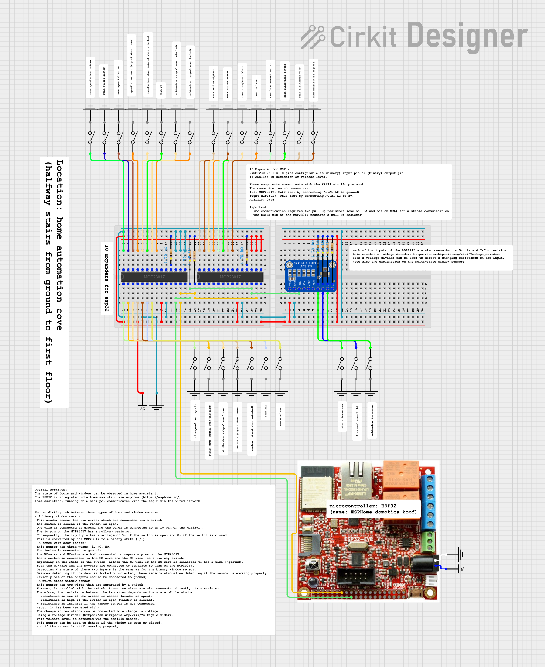 Open Project in Cirkit Designer
Explore Projects Built with MCP73831
Open Project in Cirkit DesignerOpen Project in Cirkit DesignerOpen Project in Cirkit DesignerOpen Project in Cirkit DesignerCommon Applications and Use Cases
- Portable electronic devices (e.g., smartphones, wearables, and handheld gadgets)
- Power banks and battery-powered tools
- IoT devices and wireless sensors
- Embedded systems requiring compact battery charging solutions
Technical Specifications
Key Technical Details
- Input Voltage Range: 3.75V to 6.0V
- Battery Regulation Voltage: 4.2V (typical)
- Charge Current: Programmable up to 500mA
- Thermal Regulation: Reduces charge current to prevent overheating
- Operating Temperature Range: -40°C to +85°C
- Package Options: SOT-23-5 (5-pin package)
- Charging Algorithm: Constant Current/Constant Voltage (CC/CV)
- Standby Current: 0.1µA (typical)
Pin Configuration and Descriptions
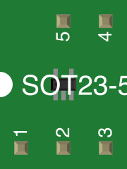
The MCP73831 is available in a 5-pin SOT-23 package. The pinout and descriptions are as follows:
| Pin Number | Pin Name | Description |
|---|---|---|
| 1 | VDD | Input supply voltage (3.75V to 6.0V). Connect to the power source. |
| 2 | STAT | Status output. Indicates charging status (active-low for charging). |
| 3 | VSS | Ground reference. Connect to the system ground. |
| 4 | PROG | Charge current programming pin. Connect a resistor to set the charge current. |
| 5 | VBAT | Battery connection pin. Connect to the positive terminal of the battery. |
Usage Instructions
How to Use the MCP73831 in a Circuit
- Power Supply: Connect the VDD pin to a regulated power source (3.75V to 6.0V). Ensure the power source can supply sufficient current for charging.
- Battery Connection: Connect the VBAT pin to the positive terminal of the Li-Ion/Li-Polymer battery. The negative terminal of the battery should be connected to ground (VSS).
- Programming Charge Current: Use a resistor (RPROG) connected between the PROG pin and ground to set the desired charge current. The charge current (ICHG) can be calculated using the formula: [ I_{CHG} = \frac{1000}{R_{PROG}} ] where ( R_{PROG} ) is in kΩ and ( I_{CHG} ) is in mA.
- Status Monitoring: The STAT pin can be used to monitor the charging status. It is active-low during charging and high-impedance when charging is complete or in standby mode.
- Thermal Considerations: Ensure proper heat dissipation by placing the MCP73831 on a PCB with adequate thermal management. Avoid placing the component near heat-sensitive parts.
Example Circuit
Below is a basic circuit diagram for using the MCP73831 to charge a single-cell Li-Ion battery:
VDD (5V) ----+----[RPROG]---- PROG
             |                |
             |                |
            STAT             VBAT ---- Battery +
             |                |
            VSS ------------- Battery -
Arduino Example Code
The MCP73831 does not require direct control from a microcontroller, but you can monitor the charging status using the STAT pin. Below is an example Arduino code to monitor the STAT pin:
// Define the STAT pin connected to the MCP73831
const int statPin = 2; // Connect STAT pin to Arduino digital pin 2

void setup() {
  pinMode(statPin, INPUT); // Set STAT pin as input
  Serial.begin(9600);      // Initialize serial communication
}

void loop() {
  int chargingStatus = digitalRead(statPin); // Read the STAT pin state

  if (chargingStatus == LOW) {
    // STAT pin is LOW, indicating charging is in progress
    Serial.println("Battery is charging...");
  } else {
    // STAT pin is HIGH (high-impedance), indicating charging is complete
    Serial.println("Charging complete or in standby mode.");
  }

  delay(1000); // Wait for 1 second before checking again
}
Troubleshooting and FAQs
Common Issues and Solutions
Problem: The battery is not charging.
- Solution: Verify that the input voltage at the VDD pin is within the specified range (3.75V to 6.0V). Check the connections to the battery and ensure the RPROG resistor is correctly calculated and installed.
Problem: The MCP73831 overheats during operation.
- Solution: Ensure proper thermal management by using a PCB with adequate copper area around the MCP73831. Reduce the charge current by increasing the RPROG resistor value if necessary.
Problem: The STAT pin does not change state.
- Solution: Check the wiring to the STAT pin and ensure it is not shorted. Verify that the battery is properly connected and not fully charged.
Problem: The charge current is incorrect.
- Solution: Recalculate the RPROG resistor value using the formula ( I_{CHG} = \frac{1000}{R_{PROG}} ). Ensure the resistor is within tolerance and properly soldered.
FAQs
Can the MCP73831 charge batteries with capacities greater than 500mAh? Yes, but ensure the charge current is set appropriately for the battery's capacity. A lower charge current may result in longer charging times.
Is the MCP73831 suitable for multi-cell battery packs? No, the MCP73831 is designed for single-cell Li-Ion/Li-Polymer batteries only.
What happens if the input voltage exceeds 6.0V? Exceeding the maximum input voltage can damage the MCP73831. Always use a regulated power source within the specified range.
Can I use the MCP73831 without a microcontroller? Yes, the MCP73831 operates autonomously and does not require a microcontroller for basic charging functionality.