Cirkit Designer Logo
Cirkit Designer
Your all-in-one circuit design IDE
Home / 
Component Documentation

How to Use SD-CARD-READER-2PINS: Examples, Pinouts, and Specs

Image of SD-CARD-READER-2PINS
Cirkit Designer LogoDesign with SD-CARD-READER-2PINS in Cirkit Designer

Introduction

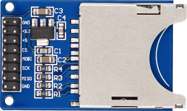
The SD-CARD-READER-2PINS is a compact electronic device designed to interface with SD (Secure Digital) cards, enabling read and write operations. This component is commonly used in embedded systems, such as digital cameras, smartphones, and DIY electronics projects, including those involving Arduino and Raspberry Pi platforms. It allows for the storage and retrieval of data such as sensor readings, images, and configuration files.

Explore Projects Built with SD-CARD-READER-2PINS

Use Cirkit Designer to design, explore, and prototype these projects online. Some projects support real-time simulation. Click "Open Project" to start designing instantly!
Arduino UNO SD Card Data Logger
Image of sd card: A project utilizing SD-CARD-READER-2PINS in a practical application
This circuit consists of an Arduino UNO connected to an SD card module. The Arduino provides power and ground to the SD module and interfaces with it using SPI communication through digital pins D10 (CS), D11 (MOSI), D12 (MISO), and D13 (SCK). The setup is intended for reading from or writing to an SD card using the Arduino.
Cirkit Designer LogoOpen Project in Cirkit Designer
Arduino UNO RFID Reader Interface Project
Image of INTERNAL DESIGN MAIN STUDY: A project utilizing SD-CARD-READER-2PINS in a practical application
This is an RFID tag reading system. An Arduino UNO is interfaced with an RFID-RC522 module using digital pins D5, D10, D11, and D13 through resistors, with direct MISO connection to D12. The system is designed to read RFID tags and handle the data with the Arduino.
Cirkit Designer LogoOpen Project in Cirkit Designer
Arduino UNO R4 WiFi Controlled Data Logger with BNO055 Sensor and Micro SD Storage
Image of Main Telemetry R4: A project utilizing SD-CARD-READER-2PINS in a practical application
This circuit features an Arduino UNO R4 WiFi microcontroller connected to a Micro SD Card Module for data storage, a BNO055 sensor for orientation data, and three red LEDs for indication purposes. The LEDs are controlled by digital pins D2, D3, and D4, and can be turned on or off using a single-pole single-throw (SPST) toggle switch connected to their common cathodes and ground. The BNO055 sensor interfaces with the Arduino via I2C communication using the SDA and SCL pins, and the Micro SD Card Module is interfaced using SPI with chip select on pin D10 and data lines on pins D11 (MOSI), D12 (MISO), and D13 (SCK).
Cirkit Designer LogoOpen Project in Cirkit Designer
ESP32-Based RFID Reader with OLED Display
Image of RFID_OLED_ESP32: A project utilizing SD-CARD-READER-2PINS in a practical application
This circuit features an ESP32 microcontroller connected to an RFID-RC522 module and an OLED display. The ESP32 communicates with the RFID reader via SPI (using pins D23, D22, D18, and D5 for MOSI, MISO, SCK, and SDA respectively) and with the OLED display through I2C (using pins D4 and D15 for SCL and SDA). All devices share a common ground and are powered by the ESP32's 3.3V output, indicating the circuit is likely used for RFID tag reading and data display on the OLED.
Cirkit Designer LogoOpen Project in Cirkit Designer

Explore Projects Built with SD-CARD-READER-2PINS

Use Cirkit Designer to design, explore, and prototype these projects online. Some projects support real-time simulation. Click "Open Project" to start designing instantly!
Image of sd card: A project utilizing SD-CARD-READER-2PINS in a practical application
Arduino UNO SD Card Data Logger
This circuit consists of an Arduino UNO connected to an SD card module. The Arduino provides power and ground to the SD module and interfaces with it using SPI communication through digital pins D10 (CS), D11 (MOSI), D12 (MISO), and D13 (SCK). The setup is intended for reading from or writing to an SD card using the Arduino.
Cirkit Designer LogoOpen Project in Cirkit Designer
Image of INTERNAL DESIGN MAIN STUDY: A project utilizing SD-CARD-READER-2PINS in a practical application
Arduino UNO RFID Reader Interface Project
This is an RFID tag reading system. An Arduino UNO is interfaced with an RFID-RC522 module using digital pins D5, D10, D11, and D13 through resistors, with direct MISO connection to D12. The system is designed to read RFID tags and handle the data with the Arduino.
Cirkit Designer LogoOpen Project in Cirkit Designer
Image of Main Telemetry R4: A project utilizing SD-CARD-READER-2PINS in a practical application
Arduino UNO R4 WiFi Controlled Data Logger with BNO055 Sensor and Micro SD Storage
This circuit features an Arduino UNO R4 WiFi microcontroller connected to a Micro SD Card Module for data storage, a BNO055 sensor for orientation data, and three red LEDs for indication purposes. The LEDs are controlled by digital pins D2, D3, and D4, and can be turned on or off using a single-pole single-throw (SPST) toggle switch connected to their common cathodes and ground. The BNO055 sensor interfaces with the Arduino via I2C communication using the SDA and SCL pins, and the Micro SD Card Module is interfaced using SPI with chip select on pin D10 and data lines on pins D11 (MOSI), D12 (MISO), and D13 (SCK).
Cirkit Designer LogoOpen Project in Cirkit Designer
Image of RFID_OLED_ESP32: A project utilizing SD-CARD-READER-2PINS in a practical application
ESP32-Based RFID Reader with OLED Display
This circuit features an ESP32 microcontroller connected to an RFID-RC522 module and an OLED display. The ESP32 communicates with the RFID reader via SPI (using pins D23, D22, D18, and D5 for MOSI, MISO, SCK, and SDA respectively) and with the OLED display through I2C (using pins D4 and D15 for SCL and SDA). All devices share a common ground and are powered by the ESP32's 3.3V output, indicating the circuit is likely used for RFID tag reading and data display on the OLED.
Cirkit Designer LogoOpen Project in Cirkit Designer

Technical Specifications

Key Technical Details

  • Supported SD Card Types: Standard SD, SDHC
  • Interface: 2-pin SPI (Serial Peripheral Interface)
  • Operating Voltage: 3.3V
  • Logic Level: 3.3V (5V tolerant with level shifter)
  • Data Transfer Speed: Dependent on SD card specifications
  • Dimensions: Varies by manufacturer

Pin Configuration and Descriptions

Pin Name Description
CS Chip Select (Active Low)
SCK Serial Clock
MOSI Master Out Slave In (Data to SD card)
MISO Master In Slave Out (Data from SD card)
VCC Supply Voltage (3.3V)
GND Ground

Note: The 2-pin designation refers to the primary communication pins (CS, SCK), not the total pin count.

Usage Instructions

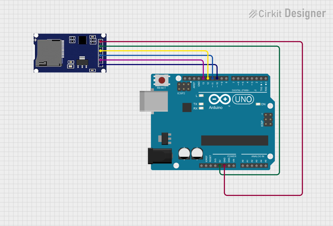
Interfacing with a Circuit

  1. Power Connections: Connect the VCC pin to a 3.3V power supply and the GND pin to the ground.
  2. SPI Connections: Connect the CS, SCK, MOSI, and MISO pins to the corresponding SPI interface pins on your microcontroller.
  3. Level Shifting: If interfacing with a 5V microcontroller, use a level shifter to protect the SD card reader.

Best Practices

  • Use a regulated 3.3V power supply to prevent damage to the SD card and reader.
  • Format the SD card to the appropriate file system (usually FAT32) before use.
  • Ensure proper ESD precautions when handling the SD card and reader.
  • Disconnect power before inserting or removing the SD card.

Example Code for Arduino UNO

#include <SPI.h>
#include <SD.h>

// Pin configuration
const int chipSelect = 10; // Change as per your CS pin connection

void setup() {
  Serial.begin(9600);
  while (!Serial) {
    ; // Wait for serial port to connect.
  }

  Serial.print("Initializing SD card...");

  // Ensure the chip select pin is set as an output
  pinMode(chipSelect, OUTPUT);

  // Check for the presence of the SD card
  if (!SD.begin(chipSelect)) {
    Serial.println("Card failed, or not present");
    // Don't continue if the initialization fails
    while (1);
  }
  Serial.println("Card initialized.");
}

void loop() {
  // Main code to read and write to the SD card goes here
}

Note: The above code initializes the SD card and checks for its presence. It serves as a starting point for further read/write operations.

Troubleshooting and FAQs

Common Issues

  • Card Not Detected: Ensure the card is inserted correctly and the pins are properly connected.
  • Read/Write Errors: Check if the SD card is formatted correctly and not locked.
  • Corrupted Data: Use a lower SPI clock speed to improve stability.

Solutions and Tips

  • Power Supply: Verify that the power supply is stable and at the correct voltage.
  • Connections: Double-check all wiring, especially the SPI connections.
  • Code Debugging: Add serial print statements to debug the code step by step.

FAQs

Q: Can I use this SD card reader with a 5V system? A: Yes, but you must use a level shifter to convert the 5V signals to 3.3V to avoid damaging the SD card reader.

Q: What is the maximum size of SD card supported? A: It typically supports up to 32GB SDHC cards, but this can vary based on the reader's firmware.

Q: How do I format the SD card for use with the reader? A: You can format the SD card to FAT32 using a computer before inserting it into the reader.

Q: Can I hot-swap the SD card while the power is on? A: It is not recommended to hot-swap the SD card as it can lead to data corruption or hardware damage. Always power down the system before inserting or removing the card.