
How to Use 0J15691: Examples, Pinouts, and Specs
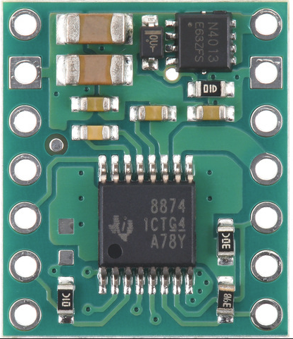
 Design with 0J15691 in Cirkit Designer
Introduction
The 0J15691 is a component manufactured by Pololu, designed for use in various electronic circuits. While the exact function of this part depends on its specific application, it is commonly utilized in robotics, automation, and embedded systems. This component is known for its reliability and compatibility with a wide range of microcontrollers and power systems.
Explore Projects Built with 0J15691
 Open Project in Cirkit Designer
 Open Project in Cirkit Designer
 Open Project in Cirkit Designer
 Open Project in Cirkit Designer
Explore Projects Built with 0J15691
Open Project in Cirkit DesignerOpen Project in Cirkit DesignerOpen Project in Cirkit DesignerOpen Project in Cirkit DesignerCommon Applications:
- Robotics and motor control systems
- Power regulation and distribution
- Embedded systems and prototyping
- General-purpose electronic circuits
Technical Specifications
Below are the key technical details for the 0J15691. For precise information, refer to the manufacturer's datasheet.
General Specifications:
- Manufacturer: Pololu
- Part Number: 0J15691
- Voltage Range: [Refer to datasheet]
- Current Rating: [Refer to datasheet]
- Power Rating: [Refer to datasheet]
- Operating Temperature: [Refer to datasheet]
Pin Configuration and Descriptions:
The pin configuration for the 0J15691 is as follows:
| Pin Number | Pin Name | Description |
|---|---|---|
| 1 | VCC | Power input (voltage supply) |
| 2 | GND | Ground connection |
| 3 | SIGNAL | Signal input/output (depends on usage) |
| 4 | ENABLE | Enable/disable functionality (optional) |
Note: The exact pinout may vary depending on the specific application of the 0J15691. Always verify with the datasheet.
Usage Instructions
How to Use the 0J15691 in a Circuit:
- Power Supply: Connect the VCC pin to a stable power source within the specified voltage range. Ensure the GND pin is connected to the circuit ground.
- Signal Input/Output: Use the SIGNAL pin for communication or control, depending on the component's role in the circuit.
- Enable Pin: If applicable, connect the ENABLE pin to a logic high signal to activate the component. Leave it unconnected or pull it low to disable.
- Bypass Capacitors: Add appropriate bypass capacitors near the VCC and GND pins to reduce noise and ensure stable operation.
Important Considerations:
- Voltage and Current Ratings: Do not exceed the specified voltage and current ratings to avoid damage.
- Heat Dissipation: If the component generates heat during operation, ensure proper ventilation or use a heatsink.
- Polarity: Double-check the polarity of connections to prevent reverse voltage damage.
Example: Using 0J15691 with Arduino UNO
If the 0J15691 is used as a motor driver or signal controller, you can interface it with an Arduino UNO. Below is an example code snippet:
// Example: Controlling 0J15691 with Arduino UNO
// This code assumes the SIGNAL pin is connected to Arduino pin 9
// and the ENABLE pin is connected to Arduino pin 8.

#define SIGNAL_PIN 9  // Define the SIGNAL pin
#define ENABLE_PIN 8  // Define the ENABLE pin

void setup() {
  pinMode(SIGNAL_PIN, OUTPUT); // Set SIGNAL pin as output
  pinMode(ENABLE_PIN, OUTPUT); // Set ENABLE pin as output

  digitalWrite(ENABLE_PIN, HIGH); // Enable the component
}

void loop() {
  digitalWrite(SIGNAL_PIN, HIGH); // Send a HIGH signal
  delay(1000);                    // Wait for 1 second
  digitalWrite(SIGNAL_PIN, LOW);  // Send a LOW signal
  delay(1000);                    // Wait for 1 second
}
Note: Modify the code based on the specific function of the 0J15691 in your circuit.
Troubleshooting and FAQs
Common Issues:
- Component Not Responding:
- Solution: Verify all connections, especially the power supply and ground. Check if the ENABLE pin is correctly set.
- Overheating:
- Solution: Ensure the component is not overloaded. Use a heatsink or improve ventilation if necessary.
- Signal Issues:
- Solution: Check the SIGNAL pin for proper voltage levels. Use an oscilloscope to debug signal integrity.
FAQs:
Q1: Can I use the 0J15691 with a 3.3V microcontroller?
A1: Yes, if the component supports a 3.3V logic level. Refer to the datasheet for compatibility.
Q2: What is the maximum current the 0J15691 can handle?
A2: Refer to the manufacturer's datasheet for the exact current rating.
Q3: Do I need external components to use the 0J15691?
A3: Depending on the application, you may need bypass capacitors, resistors, or heatsinks.
For further details, consult the Pololu datasheet for the 0J15691.