Cirkit Designer Logo
Cirkit Designer
Your all-in-one circuit design IDE
Home / 
Component Documentation

How to Use SSR-40A: Examples, Pinouts, and Specs

Image of SSR-40A
Cirkit Designer LogoDesign with SSR-40A in Cirkit Designer

Introduction

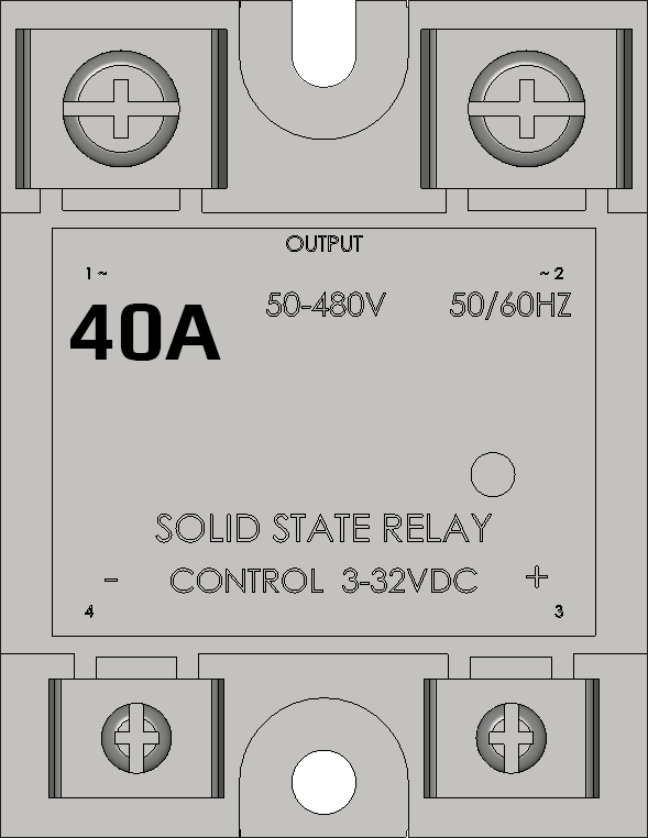
The SSR-40A is a Solid State Relay (SSR) designed for switching electrical loads up to 40 Amps. Unlike traditional electromechanical relays, the SSR-40A uses semiconductor components to perform switching operations, eliminating the need for moving parts. This results in faster switching speeds, reduced wear and tear, and a longer operational lifespan. The SSR-40A is ideal for applications requiring high reliability and silent operation.

Explore Projects Built with SSR-40A

Use Cirkit Designer to design, explore, and prototype these projects online. Some projects support real-time simulation. Click "Open Project" to start designing instantly!
Temperature-Controlled Heating System with SSR and Titanium Resistor
Image of Wire Cut Four Slider 33-2 & 33-3 (Old): A project utilizing SSR-40A in a practical application
This circuit is a temperature control system that uses a temperature controller to regulate a heating titanium resistor via a solid-state relay (SSR). The power transformer supplies the necessary voltage to the temperature controller, which in turn controls the SSR to manage the heating element.
Cirkit Designer LogoOpen Project in Cirkit Designer
Satellite-Based Timing and Navigation System with SDR and Atomic Clock Synchronization
Image of GPS 시스템 측정 구성도_Confirm: A project utilizing SSR-40A in a practical application
This circuit appears to be a complex system involving power supply management, GPS and timing synchronization, and data communication. It includes a SI-TEX G1 Satellite Compass for GPS data, an XHTF1021 Atomic Rubidium Clock for precise timing, and Ettus USRP B200 units for software-defined radio communication. Power is supplied through various SMPS units and distributed via terminal blocks and DC jacks. Data communication is facilitated by Beelink MINI S12 N95 computers, RS232 splitters, and a 1000BASE-T Media Converter for network connectivity. RF Directional Couplers are used to interface antennas with the USRP units, and the entire system is likely contained within cases for protection and organization.
Cirkit Designer LogoOpen Project in Cirkit Designer
PID Temperature Control System with Thermocouple and SSR
Image of IR: A project utilizing SSR-40A in a practical application
This circuit is a temperature control system that uses a thermocouple to measure temperature and a PID controller to regulate it. The PID controller drives a solid-state relay (SSR) to control an external load, with power supplied through an AC inlet socket.
Cirkit Designer LogoOpen Project in Cirkit Designer
Satellite Compass and Network-Integrated GPS Data Processing System
Image of GPS 시스템 측정 구성도_241016: A project utilizing SSR-40A in a practical application
This circuit comprises a satellite compass, a mini PC, two GPS antennas, power supplies, a network switch, media converters, and an atomic rubidium clock. The satellite compass is powered by a triple output DC power supply and interfaces with an RS232 splitter for 1PPS signals. The mini PCs are connected to the USRP B200 devices via USB for data and power, and to media converters via Ethernet, which in turn connect to a network switch using fiber optic links. The antennas are connected to the USRP B200s through RF directional couplers, and the atomic clock provides a 1PPS input to the RS232 splitter.
Cirkit Designer LogoOpen Project in Cirkit Designer

Explore Projects Built with SSR-40A

Use Cirkit Designer to design, explore, and prototype these projects online. Some projects support real-time simulation. Click "Open Project" to start designing instantly!
Image of Wire Cut Four Slider 33-2 & 33-3 (Old): A project utilizing SSR-40A in a practical application
Temperature-Controlled Heating System with SSR and Titanium Resistor
This circuit is a temperature control system that uses a temperature controller to regulate a heating titanium resistor via a solid-state relay (SSR). The power transformer supplies the necessary voltage to the temperature controller, which in turn controls the SSR to manage the heating element.
Cirkit Designer LogoOpen Project in Cirkit Designer
Image of GPS 시스템 측정 구성도_Confirm: A project utilizing SSR-40A in a practical application
Satellite-Based Timing and Navigation System with SDR and Atomic Clock Synchronization
This circuit appears to be a complex system involving power supply management, GPS and timing synchronization, and data communication. It includes a SI-TEX G1 Satellite Compass for GPS data, an XHTF1021 Atomic Rubidium Clock for precise timing, and Ettus USRP B200 units for software-defined radio communication. Power is supplied through various SMPS units and distributed via terminal blocks and DC jacks. Data communication is facilitated by Beelink MINI S12 N95 computers, RS232 splitters, and a 1000BASE-T Media Converter for network connectivity. RF Directional Couplers are used to interface antennas with the USRP units, and the entire system is likely contained within cases for protection and organization.
Cirkit Designer LogoOpen Project in Cirkit Designer
Image of IR: A project utilizing SSR-40A in a practical application
PID Temperature Control System with Thermocouple and SSR
This circuit is a temperature control system that uses a thermocouple to measure temperature and a PID controller to regulate it. The PID controller drives a solid-state relay (SSR) to control an external load, with power supplied through an AC inlet socket.
Cirkit Designer LogoOpen Project in Cirkit Designer
Image of GPS 시스템 측정 구성도_241016: A project utilizing SSR-40A in a practical application
Satellite Compass and Network-Integrated GPS Data Processing System
This circuit comprises a satellite compass, a mini PC, two GPS antennas, power supplies, a network switch, media converters, and an atomic rubidium clock. The satellite compass is powered by a triple output DC power supply and interfaces with an RS232 splitter for 1PPS signals. The mini PCs are connected to the USRP B200 devices via USB for data and power, and to media converters via Ethernet, which in turn connect to a network switch using fiber optic links. The antennas are connected to the USRP B200s through RF directional couplers, and the atomic clock provides a 1PPS input to the RS232 splitter.
Cirkit Designer LogoOpen Project in Cirkit Designer

Common Applications and Use Cases

  • Industrial automation and control systems
  • Heating, ventilation, and air conditioning (HVAC) systems
  • Motor control and speed regulation
  • Lighting control in commercial and residential settings
  • Temperature control in ovens, furnaces, and other heating devices

Technical Specifications

The SSR-40A is designed to handle high-power loads efficiently while maintaining safety and reliability. Below are its key technical details:

General Specifications

Parameter Value
Load Current Rating 40 Amps
Load Voltage Range 24V AC to 380V AC
Control Voltage Range 3V DC to 32V DC
Trigger Current ≤ 7.5 mA
On-State Voltage Drop ≤ 1.6V
Isolation Voltage ≥ 2500V AC
Operating Temperature -30°C to +80°C
Switching Speed ≤ 10 ms
Mounting Type Panel Mount

Pin Configuration and Descriptions

The SSR-40A has four terminals, as described in the table below:

Pin Number Label Description
1 Input (+) Positive terminal for the DC control signal
2 Input (-) Negative terminal for the DC control signal
3 Load (AC ~) One terminal of the AC load to be switched
4 Load (AC ~) The other terminal of the AC load to be switched

Usage Instructions

How to Use the SSR-40A in a Circuit

  1. Control Signal Connection: Connect the DC control signal to the input terminals (Pin 1 and Pin 2). Ensure the control voltage is within the specified range (3V DC to 32V DC).
  2. Load Connection: Connect the AC load to the load terminals (Pin 3 and Pin 4). The load voltage must be within the range of 24V AC to 380V AC.
  3. Power Supply: Ensure the power supply for the load and the control signal are properly isolated and meet the relay's specifications.
  4. Mounting: Secure the SSR-40A to a heat sink or panel to dissipate heat effectively, especially when operating at high currents.

Important Considerations and Best Practices

  • Heat Dissipation: Use a heat sink or cooling fan to prevent overheating, as the SSR-40A generates heat during operation.
  • Snubber Circuit: For inductive loads (e.g., motors), use a snubber circuit to suppress voltage spikes and protect the relay.
  • Control Signal Isolation: Use an optocoupler or similar isolation device to protect the control circuit from high voltages.
  • Wiring: Use appropriately rated wires and connectors to handle the high current and voltage.

Example: Controlling an AC Load with Arduino UNO

The SSR-40A can be easily controlled using an Arduino UNO. Below is an example circuit and code to toggle an AC load (e.g., a light bulb) using a digital pin.

Circuit Diagram

  1. Connect the SSR-40A's input terminals:
    • Pin 1 (Input +) to Arduino digital pin 9.
    • Pin 2 (Input -) to Arduino GND.
  2. Connect the AC load to the SSR-40A's load terminals (Pin 3 and Pin 4).
  3. Ensure the AC load and Arduino share a common ground.

Arduino Code

// Define the pin connected to the SSR control input
const int ssrPin = 9;

void setup() {
  // Set the SSR pin as an output
  pinMode(ssrPin, OUTPUT);
}

void loop() {
  // Turn the SSR (and the connected load) ON
  digitalWrite(ssrPin, HIGH);
  delay(5000); // Keep the load ON for 5 seconds

  // Turn the SSR (and the connected load) OFF
  digitalWrite(ssrPin, LOW);
  delay(5000); // Keep the load OFF for 5 seconds
}

Troubleshooting and FAQs

Common Issues and Solutions

  1. SSR Not Switching the Load

    • Cause: Insufficient control voltage or current.
    • Solution: Verify that the control voltage is within the range of 3V DC to 32V DC and the trigger current is sufficient.
  2. Excessive Heat Generation

    • Cause: High load current without proper heat dissipation.
    • Solution: Install a heat sink or cooling fan to manage heat effectively.
  3. Load Not Turning Off Completely

    • Cause: Leakage current in the SSR.
    • Solution: Ensure the load's minimum operating current is higher than the SSR's leakage current.
  4. Voltage Spikes or Noise

    • Cause: Inductive loads causing back EMF.
    • Solution: Use a snubber circuit or varistor to suppress voltage spikes.

FAQs

Q1: Can the SSR-40A be used with DC loads?
A1: No, the SSR-40A is designed for AC loads only. For DC loads, use a DC-specific SSR.

Q2: What happens if the control voltage exceeds 32V DC?
A2: Exceeding the control voltage range can damage the SSR. Always ensure the control voltage stays within the specified range.

Q3: Can I use the SSR-40A without a heat sink?
A3: While possible for low-current applications, it is strongly recommended to use a heat sink for currents above 10A to prevent overheating.

Q4: Is the SSR-40A polarity-sensitive on the load side?
A4: No, the load terminals (Pin 3 and Pin 4) are not polarity-sensitive, as the SSR is designed for AC loads.