Cirkit Designer Logo
Cirkit Designer
Your all-in-one circuit design IDE
Home / 
Component Documentation

How to Use stepper motor driver: Examples, Pinouts, and Specs

Image of stepper motor driver
Cirkit Designer LogoDesign with stepper motor driver in Cirkit Designer

Introduction

A stepper motor driver is an electronic device designed to drive a stepper motor, which is a type of electric motor that divides a full rotation into a number of equal steps. The driver controls the current sent to the motor coils, enabling precise control of the motor in both position and speed. Stepper motor drivers are widely used in CNC machines, 3D printers, robotics, and other applications where precise motion control is required.

Explore Projects Built with stepper motor driver

Use Cirkit Designer to design, explore, and prototype these projects online. Some projects support real-time simulation. Click "Open Project" to start designing instantly!
Arduino-Controlled Stepper and DC Motor with Relay Switching
Image of Conveyor Belt & Capping Motor: A project utilizing stepper motor driver in a practical application
This circuit controls a Nema 17 stepper motor using a DRV8825 driver module, with an Arduino UNO microcontroller dictating the step and direction. Additionally, the circuit can switch a DC motor on and off using a relay module controlled by the Arduino. The power supply provides the necessary voltage for the relay and the motor driver, which in turn powers the stepper motor, while the Arduino's firmware defines the motor's stepping behavior and the relay's switching to control the DC motor.
Cirkit Designer LogoOpen Project in Cirkit Designer
Arduino-Controlled Stepper Motor with LCD Interface and Rotary Encoder
Image of AC Servo Motor: A project utilizing stepper motor driver in a practical application
This circuit is designed to control a bipolar stepper motor using an Arduino Mega 2560 microcontroller and a STEPPERONLINE DM542T driver. The Arduino interfaces with a 20x4 LCD display over I2C for user feedback, a membrane matrix keypad for user input, and a rotary encoder for precise control inputs. The power supply provides the necessary voltage and current to drive the stepper motor through the DM542T driver.
Cirkit Designer LogoOpen Project in Cirkit Designer
Arduino UNO-Based Stepper Motor Controller with Rotary Encoder and Key Switch
Image of Attenuator with 2 Buttons: A project utilizing stepper motor driver in a practical application
This circuit controls a bipolar stepper motor using an Arduino UNO and a DRV8825 stepper motor driver. The Arduino reads inputs from a rotary encoder and a key switch module to manage the motor's direction and steps, powered by a 12V power supply.
Cirkit Designer LogoOpen Project in Cirkit Designer
Stepper Motor Control System with TB6600 Driver and DKC-1A Controller
Image of Copy of Copy of PLC-Based Step Motor Speed and Direction Control System: A project utilizing stepper motor driver in a practical application
This circuit controls a bipolar stepper motor using a tb6600 micro stepping motor driver and a DKC-1A stepper motor controller. The system is powered by a 24VDC power supply and includes a relay module for additional control functionalities.
Cirkit Designer LogoOpen Project in Cirkit Designer

Explore Projects Built with stepper motor driver

Use Cirkit Designer to design, explore, and prototype these projects online. Some projects support real-time simulation. Click "Open Project" to start designing instantly!
Image of Conveyor Belt & Capping Motor: A project utilizing stepper motor driver in a practical application
Arduino-Controlled Stepper and DC Motor with Relay Switching
This circuit controls a Nema 17 stepper motor using a DRV8825 driver module, with an Arduino UNO microcontroller dictating the step and direction. Additionally, the circuit can switch a DC motor on and off using a relay module controlled by the Arduino. The power supply provides the necessary voltage for the relay and the motor driver, which in turn powers the stepper motor, while the Arduino's firmware defines the motor's stepping behavior and the relay's switching to control the DC motor.
Cirkit Designer LogoOpen Project in Cirkit Designer
Image of AC Servo Motor: A project utilizing stepper motor driver in a practical application
Arduino-Controlled Stepper Motor with LCD Interface and Rotary Encoder
This circuit is designed to control a bipolar stepper motor using an Arduino Mega 2560 microcontroller and a STEPPERONLINE DM542T driver. The Arduino interfaces with a 20x4 LCD display over I2C for user feedback, a membrane matrix keypad for user input, and a rotary encoder for precise control inputs. The power supply provides the necessary voltage and current to drive the stepper motor through the DM542T driver.
Cirkit Designer LogoOpen Project in Cirkit Designer
Image of Attenuator with 2 Buttons: A project utilizing stepper motor driver in a practical application
Arduino UNO-Based Stepper Motor Controller with Rotary Encoder and Key Switch
This circuit controls a bipolar stepper motor using an Arduino UNO and a DRV8825 stepper motor driver. The Arduino reads inputs from a rotary encoder and a key switch module to manage the motor's direction and steps, powered by a 12V power supply.
Cirkit Designer LogoOpen Project in Cirkit Designer
Image of Copy of Copy of PLC-Based Step Motor Speed and Direction Control System: A project utilizing stepper motor driver in a practical application
Stepper Motor Control System with TB6600 Driver and DKC-1A Controller
This circuit controls a bipolar stepper motor using a tb6600 micro stepping motor driver and a DKC-1A stepper motor controller. The system is powered by a 24VDC power supply and includes a relay module for additional control functionalities.
Cirkit Designer LogoOpen Project in Cirkit Designer

Technical Specifications

Key Technical Details

  • Input Voltage Range: Typically from 8V to 35V (varies by model)
  • Output Current: Up to 2A per coil (varies by model)
  • Microstepping Support: Full, 1/2, 1/4, 1/8, etc. (model dependent)
  • Logic Input Voltage: 3.3V to 5V (compatible with most microcontrollers)

Pin Configuration and Descriptions

Pin Name Description
VDD Logic supply voltage (3.3V to 5V)
GND Ground connection
VMOT Motor supply voltage (8V to 35V)
1A, 1B Motor coil 1 connections
2A, 2B Motor coil 2 connections
STEP Step input (pulses to move the motor)
DIR Direction input (high for one direction, low for the opposite)
EN Enable input (active low to enable the driver)
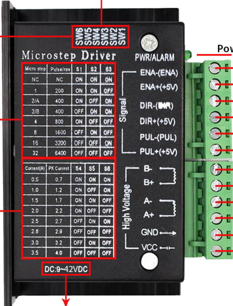
MS1, MS2, MS3 Microstepping configuration pins (logic level sets microstepping mode)
FAULT Fault output (active low indicates a fault condition)

Usage Instructions

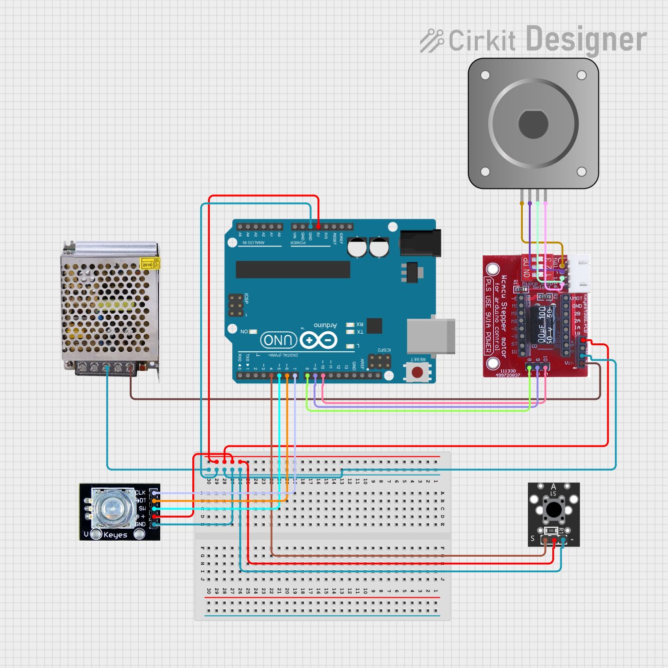
Connecting the Stepper Motor Driver to a Circuit

  1. Connect the motor coils to the driver's 1A, 1B, 2A, and 2B pins.
  2. Supply the logic voltage (VDD) and ground (GND) from the microcontroller to the driver.
  3. Connect the motor power supply to VMOT and ground.
  4. Set the desired microstepping resolution by configuring the MS1, MS2, and MS3 pins.
  5. Connect the STEP and DIR pins to the microcontroller's digital output pins.

Important Considerations and Best Practices

  • Ensure that the power supply voltage and current capabilities match the requirements of the stepper motor and driver.
  • Use appropriate heat sinking or cooling for the driver if operating at high currents.
  • Configure microstepping according to the precision and smoothness required for the application.
  • Always de-energize the circuit before making or changing connections to prevent damage.

Example Code for Arduino UNO

// Define the connection pins
const int stepPin = 2; // STEP pin connected to digital pin 2
const int dirPin = 3;  // DIR pin connected to digital pin 3

void setup() {
  // Set the pin modes
  pinMode(stepPin, OUTPUT);
  pinMode(dirPin, OUTPUT);
}

void loop() {
  // Set the direction
  digitalWrite(dirPin, HIGH); // Set to HIGH for one direction

  // Move the motor with a simple stepping pattern
  for (int i = 0; i < 200; i++) {
    // Trigger one step forward
    digitalWrite(stepPin, HIGH);
    delayMicroseconds(1000); // Wait for 1000 microseconds
    digitalWrite(stepPin, LOW);
    delayMicroseconds(1000); // Wait for 1000 microseconds
  }

  delay(1000); // Wait for a second

  // Change direction
  digitalWrite(dirPin, LOW); // Set to LOW for the opposite direction

  // Move the motor in the opposite direction
  for (int i = 0; i < 200; i++) {
    // Trigger one step backward
    digitalWrite(stepPin, HIGH);
    delayMicroseconds(1000); // Wait for 1000 microseconds
    digitalWrite(stepPin, LOW);
    delayMicroseconds(1000); // Wait for 1000 microseconds
  }

  delay(1000); // Wait for a second
}

Troubleshooting and FAQs

Common Issues

  • Motor not moving: Check power supply, connections, and ensure the enable pin is set correctly.
  • Motor stalling or skipping steps: This may be due to insufficient current, overloading, or incorrect microstepping settings.
  • Overheating: Ensure proper heat dissipation and check if the current settings are too high.

Solutions and Tips for Troubleshooting

  • Verify all connections are secure and correct.
  • Use a multimeter to check the power supply voltage and current.
  • Adjust the current limit according to the motor's specifications.
  • Ensure the microcontroller's code matches the desired motor behavior.

FAQs

Q: Can I use a stepper motor driver with any stepper motor? A: While many drivers are quite versatile, always check that the driver's voltage and current ratings are compatible with the motor.

Q: What is microstepping and why is it important? A: Microstepping divides a full step into smaller steps for smoother motion and increased resolution. It's important for applications requiring precise positioning.

Q: How do I adjust the current limit on the driver? A: This depends on the specific driver model. Some have a potentiometer that can be adjusted with a screwdriver, while others may require setting via software or digital inputs.

Remember to always consult the specific datasheet for your stepper motor driver model for the most accurate and detailed information.