Cirkit Designer
Your all-in-one circuit design IDE
Home /
Component Documentation
How to Use MAX6675 Module: Examples, Pinouts, and Specs
Introduction
The MAX6675 module is a digital thermocouple temperature sensor designed to measure temperatures ranging from 0°C to 1024°C. It provides a digital output via the Serial Peripheral Interface (SPI), making it an ideal choice for applications requiring precise temperature measurements. Common use cases include industrial temperature monitoring, HVAC systems, and scientific research.
Explore Projects Built with MAX6675 Module
ESP8266 NodeMCU Controlled Multi-Channel Thermocouple Interface

This circuit is designed to interface multiple MAX6675 thermocouple-to-digital converter modules with an ESP8266 NodeMCU microcontroller. Each MAX6675 module is connected to a temperature sensor and the ESP8266 is configured to communicate with the modules via SPI to read temperature data. The ESP8266 NodeMCU manages the chip select (CS) lines individually for each MAX6675 module, allowing for multiple temperature readings from different sensors.
Arduino Mega 2560 Based Multi-Channel Thermocouple Reader

This circuit is designed to interface with multiple MAX6675 thermocouple-to-digital converter modules using an Arduino Mega 2560 as the central processing unit. The Arduino reads temperature data from the MAX6675 modules over a shared SPI bus, with individual chip select (CS) lines for each module to enable multiplexing. The circuit is likely used for monitoring multiple temperature points, possibly in an industrial setting where precise temperature control and monitoring are critical.
Arduino Mega 2560 and MAX6675 Thermocouple Temperature Sensor
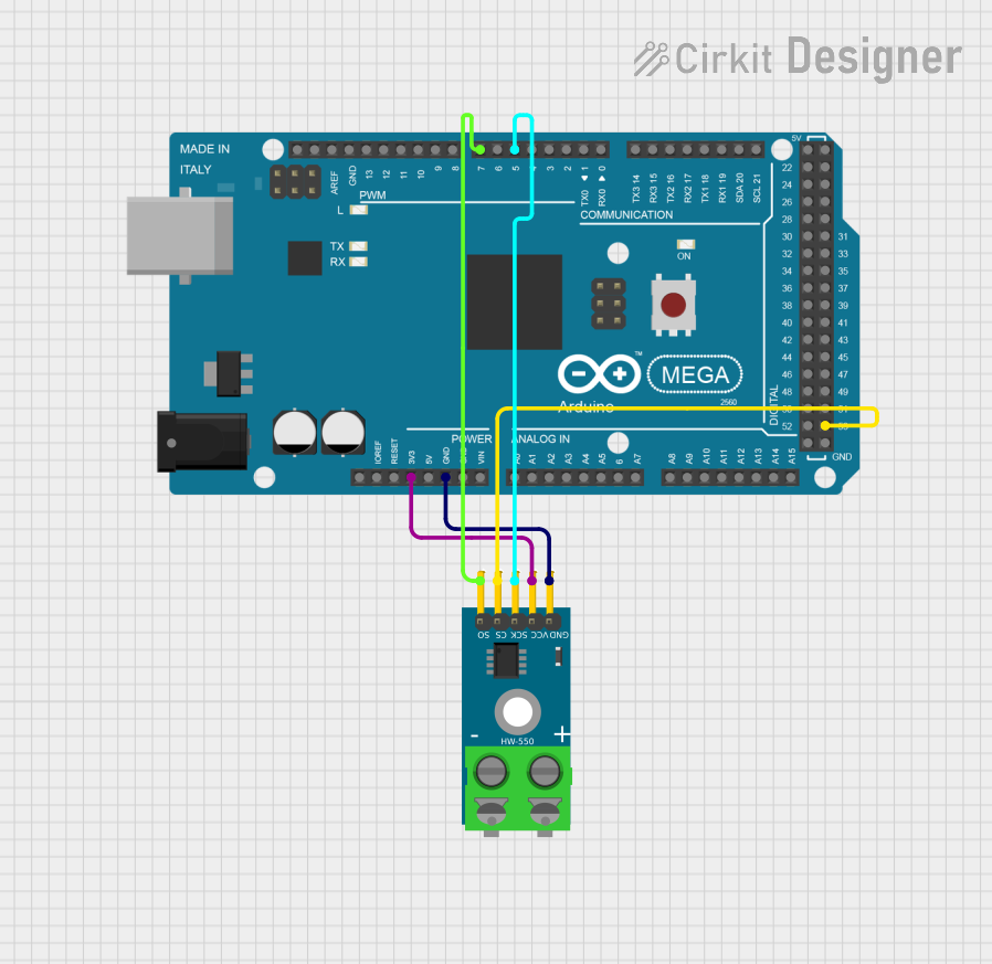
This circuit consists of an Arduino Mega 2560 microcontroller connected to a MAX6675 thermocouple temperature sensor module. The Arduino provides power to the MAX6675 module and reads temperature data via digital pins, enabling temperature monitoring and data acquisition.
ESP8266 NodeMCU with MAX6675 Thermocouple Interface for Temperature Monitoring
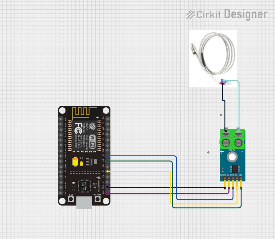
This circuit is designed to measure temperature using a Type K thermocouple connected to a MAX6675 module, which digitizes the temperature reading. The MAX6675 module interfaces with an ESP8266 NodeMCU microcontroller over a SPI connection, using D5 (SCK), D6 (SO), and D8 (CS) for clock, data output, and chip select, respectively. The ESP8266 is responsible for processing the temperature data, which can then be used for monitoring, control, or communication purposes.
Explore Projects Built with MAX6675 Module
ESP8266 NodeMCU Controlled Multi-Channel Thermocouple Interface
This circuit is designed to interface multiple MAX6675 thermocouple-to-digital converter modules with an ESP8266 NodeMCU microcontroller. Each MAX6675 module is connected to a temperature sensor and the ESP8266 is configured to communicate with the modules via SPI to read temperature data. The ESP8266 NodeMCU manages the chip select (CS) lines individually for each MAX6675 module, allowing for multiple temperature readings from different sensors.
Arduino Mega 2560 Based Multi-Channel Thermocouple Reader
This circuit is designed to interface with multiple MAX6675 thermocouple-to-digital converter modules using an Arduino Mega 2560 as the central processing unit. The Arduino reads temperature data from the MAX6675 modules over a shared SPI bus, with individual chip select (CS) lines for each module to enable multiplexing. The circuit is likely used for monitoring multiple temperature points, possibly in an industrial setting where precise temperature control and monitoring are critical.
Arduino Mega 2560 and MAX6675 Thermocouple Temperature Sensor
This circuit consists of an Arduino Mega 2560 microcontroller connected to a MAX6675 thermocouple temperature sensor module. The Arduino provides power to the MAX6675 module and reads temperature data via digital pins, enabling temperature monitoring and data acquisition.
ESP8266 NodeMCU with MAX6675 Thermocouple Interface for Temperature Monitoring
This circuit is designed to measure temperature using a Type K thermocouple connected to a MAX6675 module, which digitizes the temperature reading. The MAX6675 module interfaces with an ESP8266 NodeMCU microcontroller over a SPI connection, using D5 (SCK), D6 (SO), and D8 (CS) for clock, data output, and chip select, respectively. The ESP8266 is responsible for processing the temperature data, which can then be used for monitoring, control, or communication purposes.
Technical Specifications
Key Technical Details
| Parameter | Value |
|---|---|
| Temperature Range | 0°C to 1024°C |
| Resolution | 0.25°C |
| Interface | SPI |
| Supply Voltage | 3.0V to 5.5V |
| Power Consumption | 1.5mA (typical) |
| Accuracy | ±2°C |
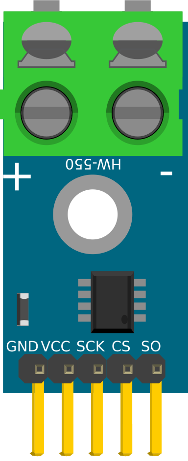
Pin Configuration and Descriptions
| Pin Number | Pin Name | Description |
|---|---|---|
| 1 | VCC | Power supply (3.0V to 5.5V) |
| 2 | GND | Ground |
| 3 | SCK | Serial Clock Input |
| 4 | CS | Chip Select (Active Low) |
| 5 | SO | Serial Data Output |
Usage Instructions
How to Use the Component in a Circuit
- Power Supply: Connect the VCC pin to a 3.0V to 5.5V power supply and the GND pin to the ground.
- SPI Interface: Connect the SCK, CS, and SO pins to the corresponding SPI pins on your microcontroller.
- Thermocouple Connection: Attach the thermocouple to the module's designated input terminals.
Important Considerations and Best Practices
- Thermocouple Type: Ensure you are using a K-type thermocouple, as the MAX6675 is calibrated for this type.
- Noise Reduction: Keep the thermocouple wires away from high-power lines to minimize noise interference.
- Temperature Range: Do not exceed the specified temperature range to avoid damaging the sensor.
Example Code for Arduino UNO
#include <SPI.h>

// Define the MAX6675 module pins
const int CS_PIN = 10;
const int SCK_PIN = 13;
const int SO_PIN = 12;

void setup() {
  // Initialize the Serial Monitor
  Serial.begin(9600);

  // Set the SPI pins
  pinMode(CS_PIN, OUTPUT);
  pinMode(SCK_PIN, OUTPUT);
  pinMode(SO_PIN, INPUT);

  // Initialize the SPI interface
  SPI.begin();

  // Set the Chip Select pin high
  digitalWrite(CS_PIN, HIGH);
}

void loop() {
  // Read temperature from MAX6675
  float temperature = readTemperature();

  // Print the temperature to the Serial Monitor
  Serial.print("Temperature: ");
  Serial.print(temperature);
  Serial.println(" °C");

  // Wait for 1 second before the next reading
  delay(1000);
}

float readTemperature() {
  // Select the MAX6675 module
  digitalWrite(CS_PIN, LOW);

  // Read 16 bits from the module
  uint16_t value = SPI.transfer16(0x00);

  // Deselect the module
  digitalWrite(CS_PIN, HIGH);

  // Check for thermocouple connection error
  if (value & 0x4) {
    return NAN; // Return NaN if there's an error
  }

  // Extract temperature data
  value >>= 3; // Remove the last 3 bits
  float temperature = value * 0.25; // Convert to Celsius

  return temperature;
}
Troubleshooting and FAQs
Common Issues Users Might Face
- No Temperature Reading: Ensure all connections are secure and the thermocouple is properly attached.
- Incorrect Temperature: Verify that you are using a K-type thermocouple and that it is within the specified temperature range.
- SPI Communication Failure: Check the SPI connections and ensure the correct pins are defined in your code.
Solutions and Tips for Troubleshooting
- Check Connections: Double-check all wiring and connections to ensure they are correct and secure.
- Use a Multimeter: Measure the voltage at the VCC and GND pins to ensure the module is receiving power.
- Verify Code: Ensure the code is correctly uploaded to the microcontroller and that the SPI pins are correctly defined.
By following this documentation, users should be able to effectively integrate and utilize the MAX6675 module in their projects, ensuring accurate and reliable temperature measurements.