How to Use Timer Relay Module: Examples, Pinouts, and Specs
Introduction
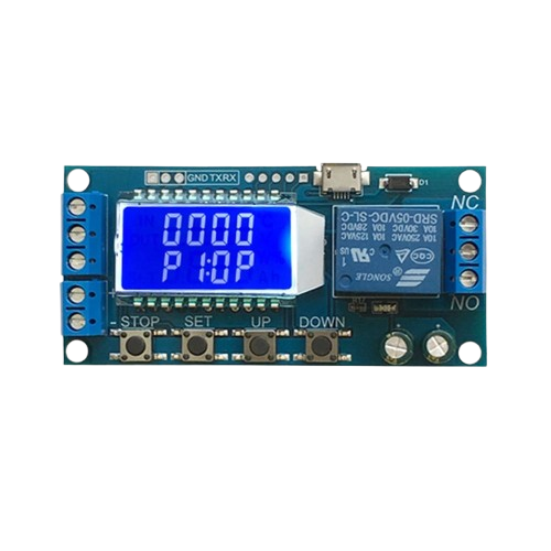
A Timer Relay Module is an electronic device designed to control the timing of electrical circuits. It operates by activating or deactivating a connected load after a user-defined time delay. This module is widely used in automation, industrial control systems, and DIY electronics projects. Its ability to precisely manage timing makes it ideal for applications such as delayed power-on, timed lighting, motor control, and other automated tasks.
Explore Projects Built with Timer Relay Module

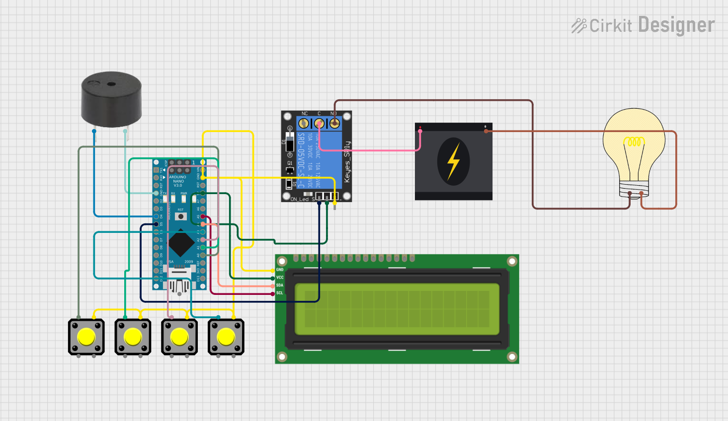
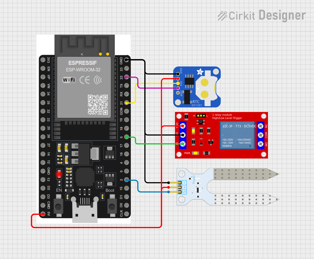
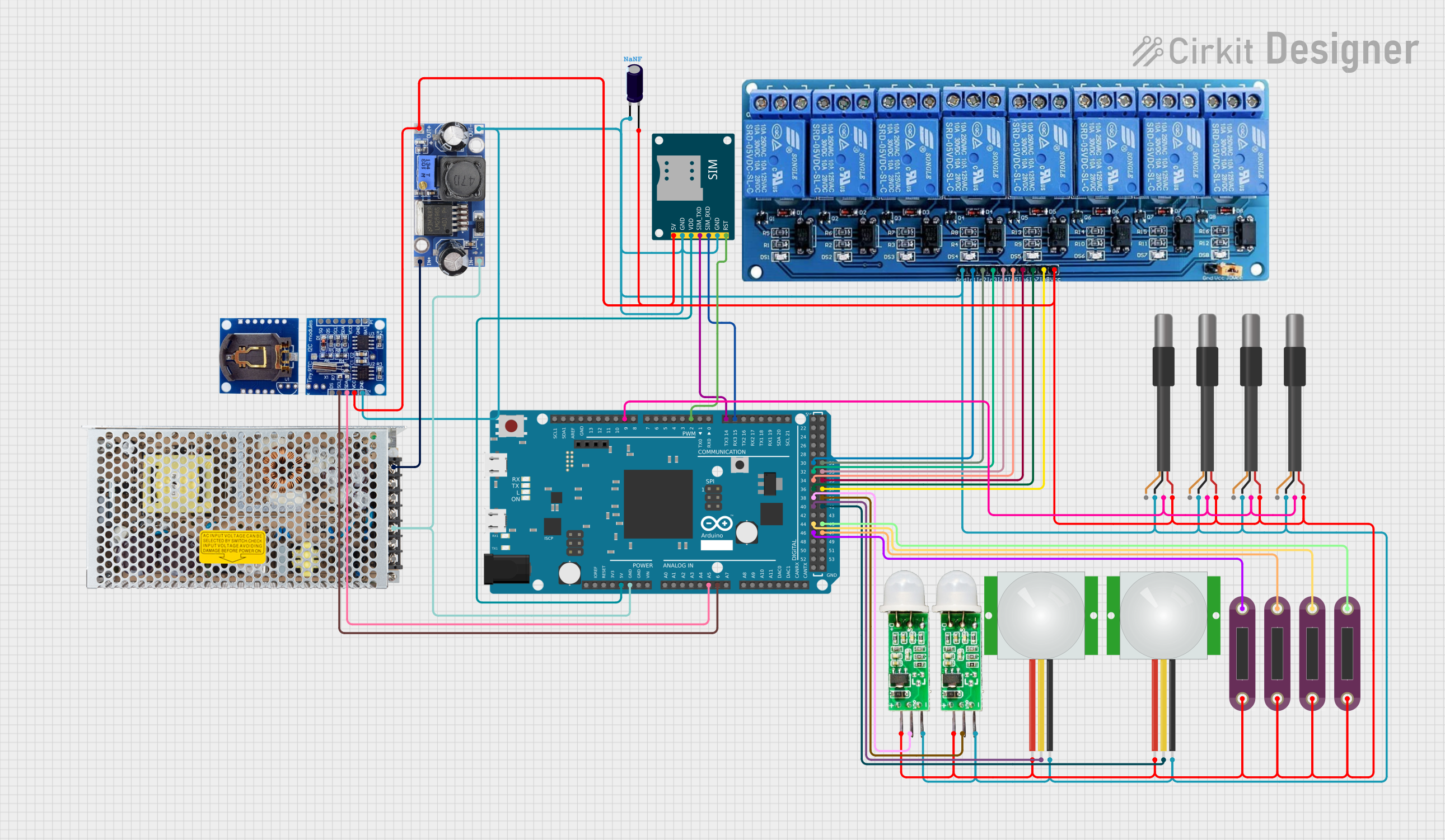
Explore Projects Built with Timer Relay Module
Common Applications
- Delayed power-on for sensitive equipment
- Timed lighting systems
- Motor control in industrial automation
- DIY electronics projects requiring timed operations
- Automatic irrigation systems
Technical Specifications
Below are the key technical details of a typical Timer Relay Module:
| Parameter | Specification |
|---|---|
| Operating Voltage | 5V, 12V, or 24V (varies by model) |
| Trigger Voltage | 3.3V to 24V (depending on model) |
| Maximum Load Current | 10A |
| Relay Type | SPDT (Single Pole Double Throw) |
| Timing Range | 0.1 seconds to 999 seconds (varies) |
| Control Modes | ON delay, OFF delay, cycle timing |
| Dimensions | Typically 50mm x 26mm x 18mm |
| Operating Temperature | -40°C to 85°C |
Pin Configuration and Descriptions
The Timer Relay Module typically has the following pin configuration:
| Pin Name | Description |
|---|---|
| VCC | Power supply input (5V, 12V, or 24V depending on the module version) |
| GND | Ground connection |
| IN | Trigger input pin (used to start the timer) |
| NO | Normally Open terminal of the relay (connect to the load for activation) |
| NC | Normally Closed terminal of the relay (connect to the load for deactivation) |
| COM | Common terminal of the relay (connect to the power source for the load) |
Usage Instructions
How to Use the Timer Relay Module in a Circuit
- Power the Module: Connect the VCC and GND pins to a suitable power source (e.g., 5V, 12V, or 24V, depending on the module version).
- Connect the Load:
- For devices that should turn ON after the timer delay, connect the load between the NO (Normally Open) and COM (Common) terminals.
- For devices that should turn OFF after the timer delay, connect the load between the NC (Normally Closed) and COM terminals.
- Set the Timing: Use the onboard potentiometer or buttons (if available) to set the desired delay time.
- Trigger the Timer: Apply a signal to the IN pin to start the timer. The relay will activate or deactivate the load based on the configured timing mode.
Important Considerations
- Ensure the power supply voltage matches the module's operating voltage to avoid damage.
- Do not exceed the maximum load current (10A) to prevent relay failure.
- Use proper insulation and wiring practices when working with high-voltage loads.
- If using the module with an Arduino or other microcontroller, ensure the trigger voltage is compatible with the IN pin.
Example: Using the Timer Relay Module with Arduino UNO
Below is an example of how to use the Timer Relay Module with an Arduino UNO to control a load with a 5-second delay:
// Example: Controlling a Timer Relay Module with Arduino UNO
// This code triggers the relay to turn ON a load after a 5-second delay.

#define RELAY_TRIGGER_PIN 7  // Pin connected to the IN pin of the Timer Relay Module

void setup() {
  pinMode(RELAY_TRIGGER_PIN, OUTPUT); // Set the relay trigger pin as an output
  digitalWrite(RELAY_TRIGGER_PIN, LOW); // Ensure the relay is initially OFF
}

void loop() {
  digitalWrite(RELAY_TRIGGER_PIN, HIGH); // Trigger the relay
  delay(5000); // Wait for 5 seconds
  digitalWrite(RELAY_TRIGGER_PIN, LOW); // Turn OFF the relay
  delay(5000); // Wait for another 5 seconds before repeating
}
Best Practices
- Use a flyback diode across the relay coil if the module does not already include one, to protect against voltage spikes.
- For inductive loads (e.g., motors), use a snubber circuit to prevent damage to the relay contacts.
- Test the module with a low-power load before connecting high-power devices.
Troubleshooting and FAQs
Common Issues and Solutions
The relay does not activate:
- Verify that the power supply voltage matches the module's requirements.
- Check the wiring connections, especially the IN pin and load terminals.
- Ensure the trigger signal is within the acceptable voltage range.
The relay activates but the load does not turn ON:
- Confirm that the load is properly connected to the NO or NC terminal and the COM terminal.
- Check the load's power source and ensure it is functioning correctly.
The timing is inaccurate:
- Recheck the timing settings on the module (e.g., potentiometer or buttons).
- Ensure the module is not exposed to extreme temperatures, which can affect timing accuracy.
The module overheats:
- Verify that the load current does not exceed the module's maximum rating (10A).
- Use a heatsink or cooling fan if the module operates continuously under high loads.
FAQs
Q: Can I use the Timer Relay Module with a 3.3V microcontroller?
A: Yes, but ensure the module's IN pin supports 3.3V logic levels. If not, use a level shifter or transistor circuit.
Q: Can the module handle AC loads?
A: Yes, the relay can control AC loads, but ensure the load's voltage and current are within the relay's specifications.
Q: How do I reset the timer?
A: To reset the timer, remove the trigger signal from the IN pin and reapply it.
Q: Can I use the module for cyclic timing (e.g., ON for 10 seconds, OFF for 5 seconds)?
A: Some Timer Relay Modules support cyclic timing modes. Check the module's datasheet or user manual for details.
By following this documentation, you can effectively use the Timer Relay Module in your projects and troubleshoot common issues with ease.