How to Use Stm32: Examples, Pinouts, and Specs
Introduction
The STM32F405RGT6 is a high-performance microcontroller from STMicroelectronics, part of the STM32 family. It is based on the ARM Cortex-M4 core, which features a floating-point unit (FPU) for efficient numerical computations. This microcontroller is designed for a wide range of applications, including embedded systems, Internet of Things (IoT) devices, industrial automation, and consumer electronics.
With its advanced peripherals, high processing power, and low power consumption, the STM32F405RGT6 is ideal for applications requiring real-time performance, complex signal processing, and connectivity.
Explore Projects Built with Stm32
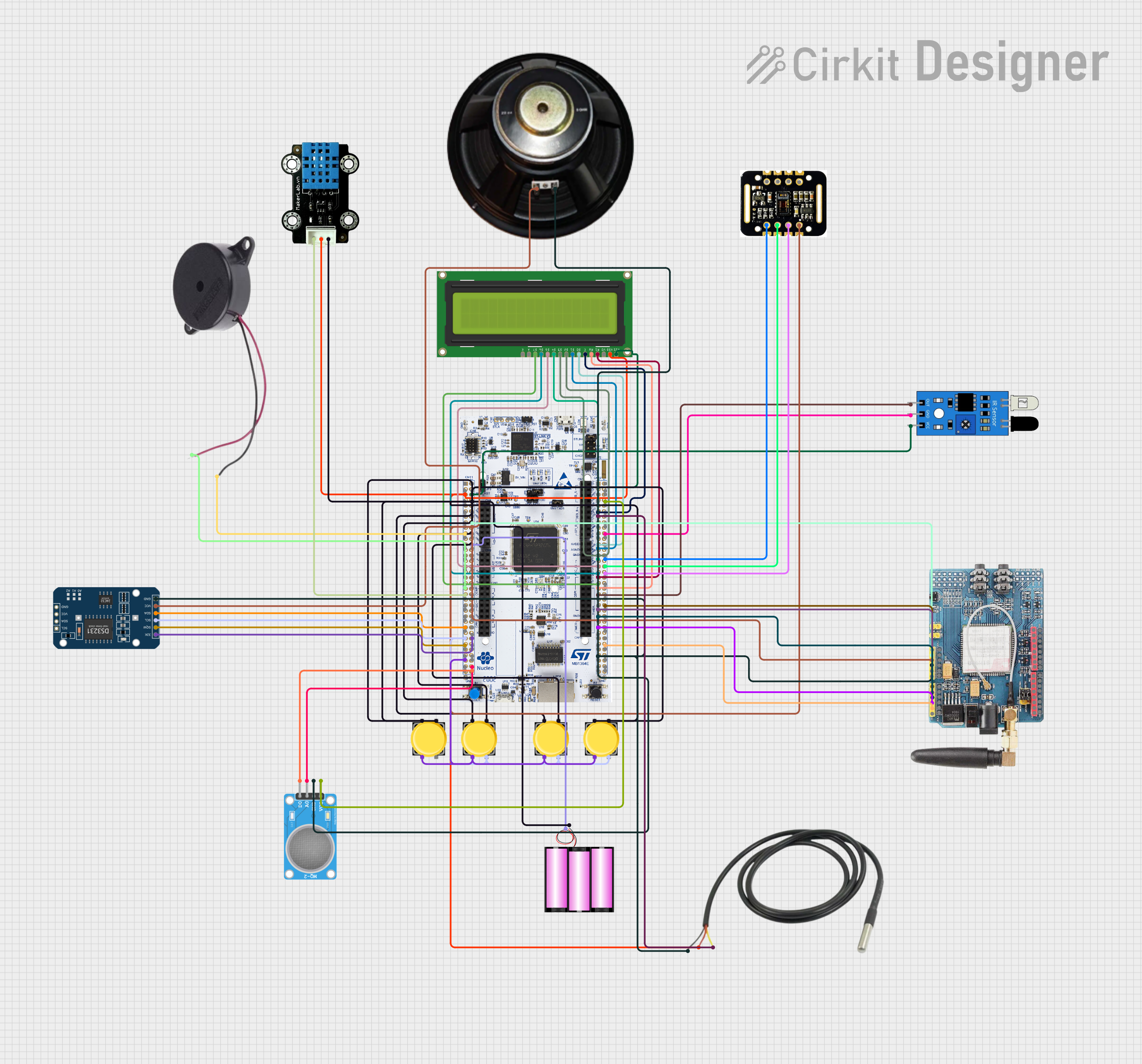
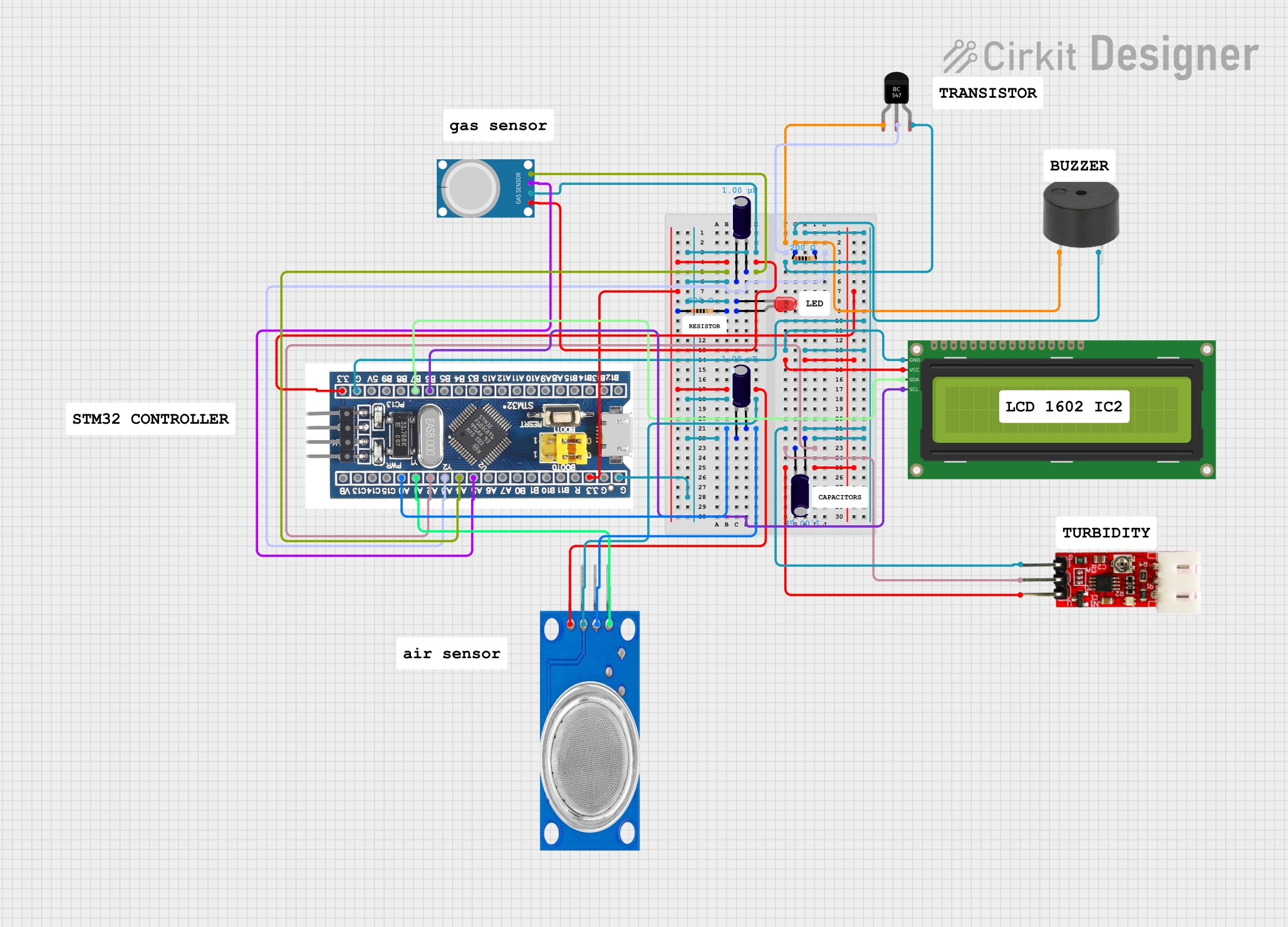


Explore Projects Built with Stm32
Common Applications
- Industrial control systems
- IoT devices and smart home applications
- Robotics and automation
- Wearable devices
- Audio processing and multimedia systems
- Data acquisition and logging systems
Technical Specifications
Key Technical Details
| Parameter | Value |
|---|---|
| Core | ARM Cortex-M4 with FPU |
| Operating Frequency | Up to 168 MHz |
| Flash Memory | 1 MB |
| SRAM | 192 KB |
| GPIO Pins | Up to 51 |
| Communication Interfaces | USART, SPI, I2C, CAN, USB OTG, SDIO |
| ADC | 12-bit, up to 16 channels |
| DAC | 12-bit, 2 channels |
| Timers | 17 timers (including advanced control timers) |
| Operating Voltage | 1.8V to 3.6V |
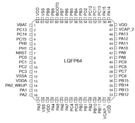
| Package | LQFP-64 (64-pin) |
| Temperature Range | -40°C to +85°C |
Pin Configuration and Descriptions
The STM32F405RGT6 comes in a 64-pin LQFP package. Below is a summary of the pin configuration:
| Pin Number | Pin Name | Function(s) | Description |
|---|---|---|---|
| 1 | VDD | Power Supply | Positive power supply (3.3V typical) |
| 2 | VSS | Ground | Ground connection |
| 3 | PA0 | GPIO/ADC_IN0 | General-purpose I/O or ADC input channel |
| 4 | PA1 | GPIO/ADC_IN1 | General-purpose I/O or ADC input channel |
| ... | ... | ... | ... |
| 64 | NRST | Reset | Active-low reset input |
For the complete pinout, refer to the STM32F405RGT6 datasheet provided by STMicroelectronics.
Usage Instructions
How to Use the STM32F405RGT6 in a Circuit
- Power Supply: Connect the VDD pin to a 3.3V power source and the VSS pin to ground. Ensure proper decoupling capacitors (e.g., 0.1 µF) are placed close to the power pins.
- Clock Configuration: Use an external crystal oscillator (e.g., 8 MHz) connected to the OSC_IN and OSC_OUT pins for precise clocking. Alternatively, the internal RC oscillator can be used.
- Programming: The STM32F405RGT6 can be programmed using the SWD (Serial Wire Debug) interface or the USART bootloader. Tools like ST-Link or USB-to-serial adapters are commonly used.
- GPIO Configuration: Configure GPIO pins as input, output, or alternate function using the STM32 HAL (Hardware Abstraction Layer) or direct register programming.
- Peripherals: Enable and configure peripherals (e.g., USART, SPI, I2C) using the STM32CubeMX tool or STM32 HAL libraries.
Important Considerations and Best Practices
- Power Supply Decoupling: Place decoupling capacitors close to the VDD and VSS pins to reduce noise and ensure stable operation.
- Reset Pin: Connect a pull-up resistor (e.g., 10 kΩ) to the NRST pin to prevent accidental resets.
- Debugging: Use the SWD interface for debugging and firmware updates.
- Clock Configuration: Ensure the clock source and PLL settings are configured correctly for the desired operating frequency.
- ESD Protection: Add ESD protection diodes on GPIO pins exposed to external connections.
Example Code for Arduino UNO Integration
Although the STM32F405RGT6 is not directly compatible with Arduino UNO, it can be programmed using the Arduino IDE with the STM32 core installed. Below is an example of blinking an LED connected to pin PA5:
// Include the STM32 HAL library
#include <Arduino.h>

// Define the LED pin
#define LED_PIN PA5

void setup() {
  // Initialize the LED pin as an output
  pinMode(LED_PIN, OUTPUT);
}

void loop() {
  // Turn the LED on
  digitalWrite(LED_PIN, HIGH);
  delay(500); // Wait for 500 ms

  // Turn the LED off
  digitalWrite(LED_PIN, LOW);
  delay(500); // Wait for 500 ms
}
To use this code:
- Install the STM32 core in the Arduino IDE.
- Select the appropriate STM32 board and upload the code.
Troubleshooting and FAQs
Common Issues and Solutions
Microcontroller Not Responding
- Cause: Incorrect power supply or missing decoupling capacitors.
- Solution: Verify the power supply voltage and ensure proper decoupling capacitors are in place.
Unable to Program the Microcontroller
- Cause: Incorrect SWD connection or bootloader configuration.
- Solution: Check the SWD connections and ensure the boot mode pins (BOOT0 and BOOT1) are configured correctly.
Peripherals Not Working
- Cause: Incorrect clock configuration or peripheral initialization.
- Solution: Verify the clock source and ensure the peripheral is properly initialized in the code.
Random Resets
- Cause: Noise on the reset pin or unstable power supply.
- Solution: Add a pull-up resistor to the NRST pin and ensure a stable power supply.
FAQs
Q: Can the STM32F405RGT6 run on 5V?
A: No, the STM32F405RGT6 operates at a voltage range of 1.8V to 3.6V. Exceeding this range may damage the microcontroller.
Q: How do I enable the floating-point unit (FPU)?
A: The FPU is enabled by default in most development environments. Ensure your compiler settings support hardware floating-point operations.
Q: Can I use the STM32F405RGT6 with Arduino libraries?
A: Yes, by installing the STM32 core in the Arduino IDE, you can use Arduino libraries and functions with the STM32F405RGT6.
Q: What is the maximum clock speed of the STM32F405RGT6?
A: The maximum clock speed is 168 MHz, achievable with proper PLL configuration.
This concludes the documentation for the STM32F405RGT6 microcontroller. For more details, refer to the official datasheet and reference manual from STMicroelectronics.