Cirkit Designer Logo
Cirkit Designer
Your all-in-one circuit design IDE
Home / 
Component Documentation

How to Use 8 push button board PCB: Examples, Pinouts, and Specs

Image of 8 push button board PCB
Cirkit Designer LogoDesign with 8 push button board PCB in Cirkit Designer

Introduction

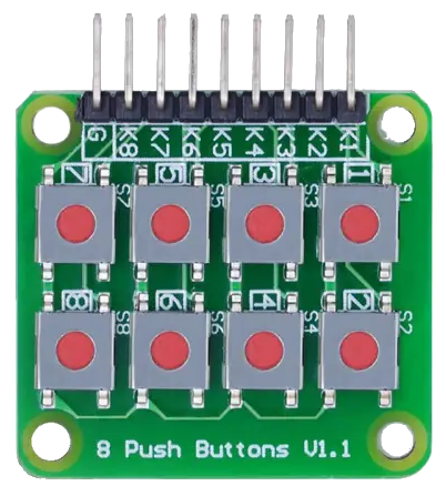
The 8 Push Button Board PCB is a versatile and compact electronic component designed to integrate eight individual push buttons into a variety of electronic projects. This board simplifies the process of adding multiple buttons without the need for extensive wiring or space-consuming setups. Common applications include user interfaces, control panels, and educational projects where multiple inputs are required.

Explore Projects Built with 8 push button board PCB

Use Cirkit Designer to design, explore, and prototype these projects online. Some projects support real-time simulation. Click "Open Project" to start designing instantly!
Pushbutton-Controlled Interface with 40-Pin Connector and UBS Power Supply
Image of connect 4: A project utilizing 8 push button board PCB in a practical application
This circuit consists of a 40-pin connector interfacing with four pushbuttons and a UBS power supply. The pushbuttons are used as inputs to the connector, which then relays the signals to other components or systems. The UBS power supply provides the necessary 24V power to the pushbuttons and the common ground for the circuit.
Cirkit Designer LogoOpen Project in Cirkit Designer
Arduino UNO Controlled LED Matrix Display with Interactive Pushbuttons
Image of Cykel: A project utilizing 8 push button board PCB in a practical application
This circuit features an Arduino UNO microcontroller connected to multiple 8x8 LED matrix displays and pushbuttons. The pushbuttons are interfaced with digital pins D2, D3, and D4 on the Arduino for input, while the LED matrices are connected to digital pins D5 through D10 for control signals. Additionally, there is a single red LED with a series resistor connected to pin D12, likely used as an indicator light.
Cirkit Designer LogoOpen Project in Cirkit Designer
Battery-Powered Multi-Button Controller with Seeed Studio nRF52840
Image of RetroBle Atari Controller: A project utilizing 8 push button board PCB in a practical application
This circuit consists of five pushbuttons connected to a Seeed Studio nRF52840 microcontroller, which is powered by a Polymer Lithium Ion Battery. Each pushbutton is connected to a different GPIO pin on the microcontroller, allowing for individual button press detection and processing.
Cirkit Designer LogoOpen Project in Cirkit Designer
24V Pushbutton Control Interface with 40-Pin Connector
Image of 4 på rad: A project utilizing 8 push button board PCB in a practical application
This circuit consists of a 24V power supply unit (PSU) connected to four pushbuttons. Each pushbutton is wired such that pressing it will send a 24V signal to a corresponding general-purpose input (GP In) on a 40-pin connector. The common return path for the pushbuttons is connected to the 0V of the PSU, which is also connected to the common (Com) for input pins on the 40-pin connector, completing the circuit for each button press.
Cirkit Designer LogoOpen Project in Cirkit Designer

Explore Projects Built with 8 push button board PCB

Use Cirkit Designer to design, explore, and prototype these projects online. Some projects support real-time simulation. Click "Open Project" to start designing instantly!
Image of connect 4: A project utilizing 8 push button board PCB in a practical application
Pushbutton-Controlled Interface with 40-Pin Connector and UBS Power Supply
This circuit consists of a 40-pin connector interfacing with four pushbuttons and a UBS power supply. The pushbuttons are used as inputs to the connector, which then relays the signals to other components or systems. The UBS power supply provides the necessary 24V power to the pushbuttons and the common ground for the circuit.
Cirkit Designer LogoOpen Project in Cirkit Designer
Image of Cykel: A project utilizing 8 push button board PCB in a practical application
Arduino UNO Controlled LED Matrix Display with Interactive Pushbuttons
This circuit features an Arduino UNO microcontroller connected to multiple 8x8 LED matrix displays and pushbuttons. The pushbuttons are interfaced with digital pins D2, D3, and D4 on the Arduino for input, while the LED matrices are connected to digital pins D5 through D10 for control signals. Additionally, there is a single red LED with a series resistor connected to pin D12, likely used as an indicator light.
Cirkit Designer LogoOpen Project in Cirkit Designer
Image of RetroBle Atari Controller: A project utilizing 8 push button board PCB in a practical application
Battery-Powered Multi-Button Controller with Seeed Studio nRF52840
This circuit consists of five pushbuttons connected to a Seeed Studio nRF52840 microcontroller, which is powered by a Polymer Lithium Ion Battery. Each pushbutton is connected to a different GPIO pin on the microcontroller, allowing for individual button press detection and processing.
Cirkit Designer LogoOpen Project in Cirkit Designer
Image of 4 på rad: A project utilizing 8 push button board PCB in a practical application
24V Pushbutton Control Interface with 40-Pin Connector
This circuit consists of a 24V power supply unit (PSU) connected to four pushbuttons. Each pushbutton is wired such that pressing it will send a 24V signal to a corresponding general-purpose input (GP In) on a 40-pin connector. The common return path for the pushbuttons is connected to the 0V of the PSU, which is also connected to the common (Com) for input pins on the 40-pin connector, completing the circuit for each button press.
Cirkit Designer LogoOpen Project in Cirkit Designer

Technical Specifications

General Features

  • Board Dimensions: Typically varies by manufacturer
  • Mounting Type: Through-hole or surface mount (depending on the model)
  • Button Type: Momentary tactile push buttons
  • Contact Rating: Varies by button specification (commonly 50mA at 12VDC)
  • Operating Temperature: Depending on the button specifications

Pin Configuration and Descriptions

Pin Number Description Notes
1 Button 1 Output Active low when button is pressed
2 Button 2 Output Active low when button is pressed
3 Button 3 Output Active low when button is pressed
4 Button 4 Output Active low when button is pressed
5 Button 5 Output Active low when button is pressed
6 Button 6 Output Active low when button is pressed
7 Button 7 Output Active low when button is pressed
8 Button 8 Output Active low when button is pressed
9 Common Ground (GND) Connect to system ground

Note: The pin configuration may vary based on the manufacturer's design. Always refer to the manufacturer's datasheet for the exact pinout.

Usage Instructions

Integration into a Circuit

  1. Power Connections: Connect the common ground (GND) pin to the ground of your power supply or system ground.
  2. Output Connections: Connect each button output to the respective input pin on your microcontroller or input circuit.
  3. Pull-up Resistors: It is recommended to use internal or external pull-up resistors on the input pins to ensure a defined logic level when the buttons are not pressed.

Best Practices

  • Debouncing: Implement software debouncing to prevent false triggering due to mechanical switch bounce.
  • Protection: Consider using current-limiting resistors to protect the microcontroller pins from overcurrent conditions.
  • Testing: Test each button individually to ensure proper functionality before integrating into a larger system.

Example Code for Arduino UNO

// Define the button pins
const int buttonPins[] = {2, 3, 4, 5, 6, 7, 8, 9};

// Setup function runs once at the start
void setup() {
  // Initialize serial communication
  Serial.begin(9600);
  
  // Set button pins as inputs with internal pull-up resistors
  for (int i = 0; i < 8; i++) {
    pinMode(buttonPins[i], INPUT_PULLUP);
  }
}

// Loop function runs repeatedly
void loop() {
  for (int i = 0; i < 8; i++) {
    // Check if the button is pressed (logic will be LOW due to pull-up)
    if (digitalRead(buttonPins[i]) == LOW) {
      // Debounce by waiting for 50 milliseconds
      delay(50);
      // Check the button state again to confirm the press
      if (digitalRead(buttonPins[i]) == LOW) {
        // Print which button was pressed
        Serial.print("Button ");
        Serial.print(i + 1);
        Serial.println(" was pressed.");
        // Wait until the button is released
        while (digitalRead(buttonPins[i]) == LOW);
      }
    }
  }
}

Note: The above code assumes that the buttons are connected to digital pins 2 through 9 on the Arduino UNO.

Troubleshooting and FAQs

Common Issues

  • Buttons not responding: Ensure that all connections are secure and the common ground is connected.
  • False triggers: Implement debouncing in the code to handle mechanical switch bounce.
  • Inconsistent behavior: Check for any soldering issues or short circuits on the PCB.

FAQs

Q: Can I use this board with a 3.3V system? A: Yes, but ensure that the button ratings are compatible with your system's voltage.

Q: How can I clean the push buttons if they become unresponsive? A: Use a contact cleaner spray designed for electronic components. Avoid applying excessive force that could damage the buttons.

Q: Are the buttons replaceable? A: This depends on the design of the PCB. Some boards may allow for button replacement if they are not permanently soldered.

For further assistance, please refer to the community forums or contact the manufacturer's support.