How to Use IRFP064: Examples, Pinouts, and Specs
Introduction
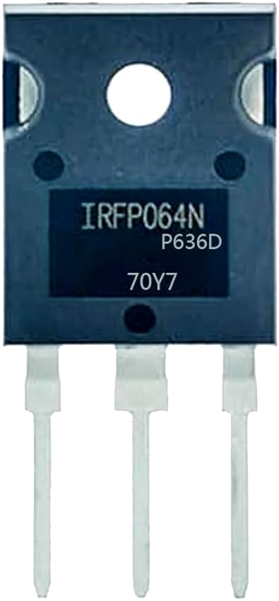
The IRFP064N is an N-channel power MOSFET manufactured by Vishay Siliconix. It is designed for high-speed switching applications and features a low on-resistance (RDS(on)) and high voltage rating. This makes it ideal for use in power management, motor control, and other high-efficiency circuits. The IRFP064N is commonly used in applications such as DC-DC converters, motor drivers, and uninterruptible power supplies (UPS).
Explore Projects Built with IRFP064
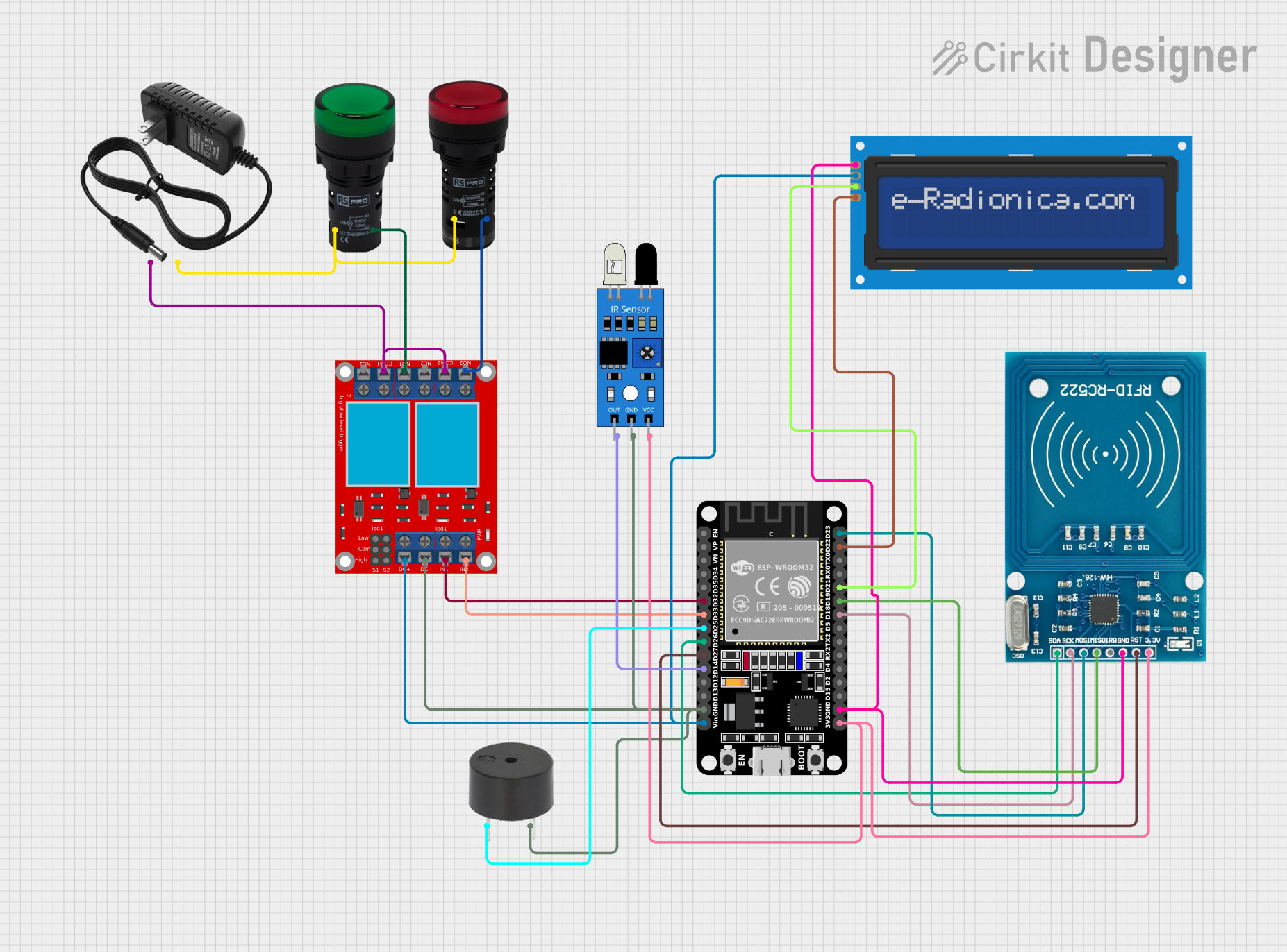

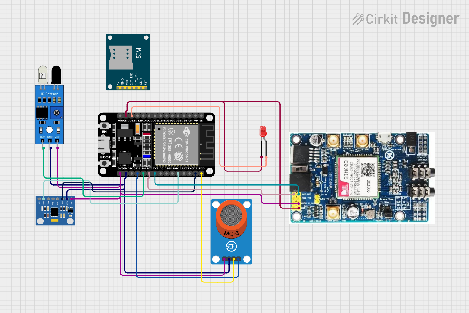

Explore Projects Built with IRFP064
Common Applications:
- DC-DC converters
- Motor control circuits
- Uninterruptible power supplies (UPS)
- High-efficiency power management systems
- Switching regulators
Technical Specifications
Below are the key technical specifications of the IRFP064N:
| Parameter | Value |
|---|---|
| Manufacturer | Vishay Siliconix |
| Part Number | IRFP064N |
| Type | N-Channel MOSFET |
| Maximum Drain-Source Voltage (VDS) | 55V |
| Maximum Gate-Source Voltage (VGS) | ±20V |
| Continuous Drain Current (ID) | 110A (at 25°C) |
| Pulsed Drain Current (IDM) | 440A |
| Power Dissipation (PD) | 200W (at 25°C) |
| On-Resistance (RDS(on)) | 0.0095Ω (typical) |
| Gate Charge (Qg) | 160nC |
| Operating Temperature Range | -55°C to +175°C |
| Package Type | TO-247 |
Pin Configuration
The IRFP064N is available in a TO-247 package with three pins. The pin configuration is as follows:
| Pin Number | Pin Name | Description |
|---|---|---|
| 1 | Gate (G) | Controls the MOSFET switching state |
| 2 | Drain (D) | Current flows into this terminal |
| 3 | Source (S) | Current flows out of this terminal |
Usage Instructions
How to Use the IRFP064N in a Circuit
- Gate Drive Voltage: Ensure the gate voltage (VGS) is within the specified range (±20V). For optimal performance, a gate voltage of 10V to 15V is recommended.
- Load Connection: Connect the load between the drain (D) and the positive supply voltage. The source (S) should be connected to ground.
- Gate Resistor: Use a gate resistor (typically 10Ω to 100Ω) to limit the inrush current and prevent damage to the gate.
- Heat Dissipation: Since the IRFP064N can handle high currents, ensure proper heat dissipation using a heatsink or active cooling.
- Protection Circuitry: Add a flyback diode across inductive loads to protect the MOSFET from voltage spikes during switching.
Example Circuit with Arduino UNO
The IRFP064N can be used with an Arduino UNO to control high-power loads such as motors or LEDs. Below is an example circuit and code:
Circuit Description:
- Connect the source (S) pin of the IRFP064N to ground.
- Connect the drain (D) pin to one terminal of the load (e.g., motor or LED).
- Connect the other terminal of the load to the positive supply voltage.
- Connect the gate (G) pin to a PWM-capable pin on the Arduino (e.g., pin 9) through a 100Ω resistor.
Example Code:
// Example code to control the IRFP064N with an Arduino UNO
// This code uses PWM to control the brightness of an LED or the speed of a motor.

const int mosfetGatePin = 9; // Connect the gate of the IRFP064N to pin 9

void setup() {
  pinMode(mosfetGatePin, OUTPUT); // Set the MOSFET gate pin as an output
}

void loop() {
  // Gradually increase the PWM signal from 0 to 255
  for (int pwmValue = 0; pwmValue <= 255; pwmValue++) {
    analogWrite(mosfetGatePin, pwmValue); // Write PWM signal to the gate
    delay(10); // Delay for smooth transition
  }

  // Gradually decrease the PWM signal from 255 to 0
  for (int pwmValue = 255; pwmValue >= 0; pwmValue--) {
    analogWrite(mosfetGatePin, pwmValue); // Write PWM signal to the gate
    delay(10); // Delay for smooth transition
  }
}
Important Considerations:
- Gate Drive Requirements: Ensure the gate drive voltage is sufficient to fully turn on the MOSFET. A logic-level MOSFET driver may be required for low-voltage control.
- Thermal Management: Use a heatsink or active cooling to prevent overheating during high-current operation.
- Inductive Loads: Always use a flyback diode across inductive loads to protect the MOSFET from voltage spikes.
Troubleshooting and FAQs
Common Issues and Solutions
MOSFET Overheating:
- Cause: Insufficient cooling or high RDS(on).
- Solution: Use a larger heatsink or active cooling. Ensure the gate voltage is high enough to minimize RDS(on).
MOSFET Not Switching:
- Cause: Insufficient gate drive voltage.
- Solution: Verify that the gate voltage is within the recommended range (10V to 15V).
Load Not Operating Properly:
- Cause: Incorrect wiring or insufficient power supply.
- Solution: Double-check the circuit connections and ensure the power supply can handle the load current.
MOSFET Damage:
- Cause: Voltage spikes or excessive current.
- Solution: Add protection components such as a flyback diode, TVS diode, or snubber circuit.
FAQs
Q: Can the IRFP064N be driven directly by a 5V microcontroller?
A: No, the IRFP064N requires a gate voltage of at least 10V to fully turn on. Use a gate driver or a logic-level MOSFET for direct control by a 5V microcontroller.
Q: What is the maximum current the IRFP064N can handle?
A: The IRFP064N can handle a continuous drain current of 110A at 25°C, but proper cooling is required to achieve this.
Q: How do I protect the IRFP064N from voltage spikes?
A: Use a flyback diode across inductive loads and consider adding a snubber circuit or TVS diode for additional protection.
Q: Can the IRFP064N be used for AC applications?
A: The IRFP064N is primarily designed for DC applications. For AC applications, consider using an H-bridge circuit or a TRIAC.
This concludes the documentation for the IRFP064N.