
How to Use HiFive1: Examples, Pinouts, and Specs
 Design with HiFive1 in Cirkit Designer
Introduction
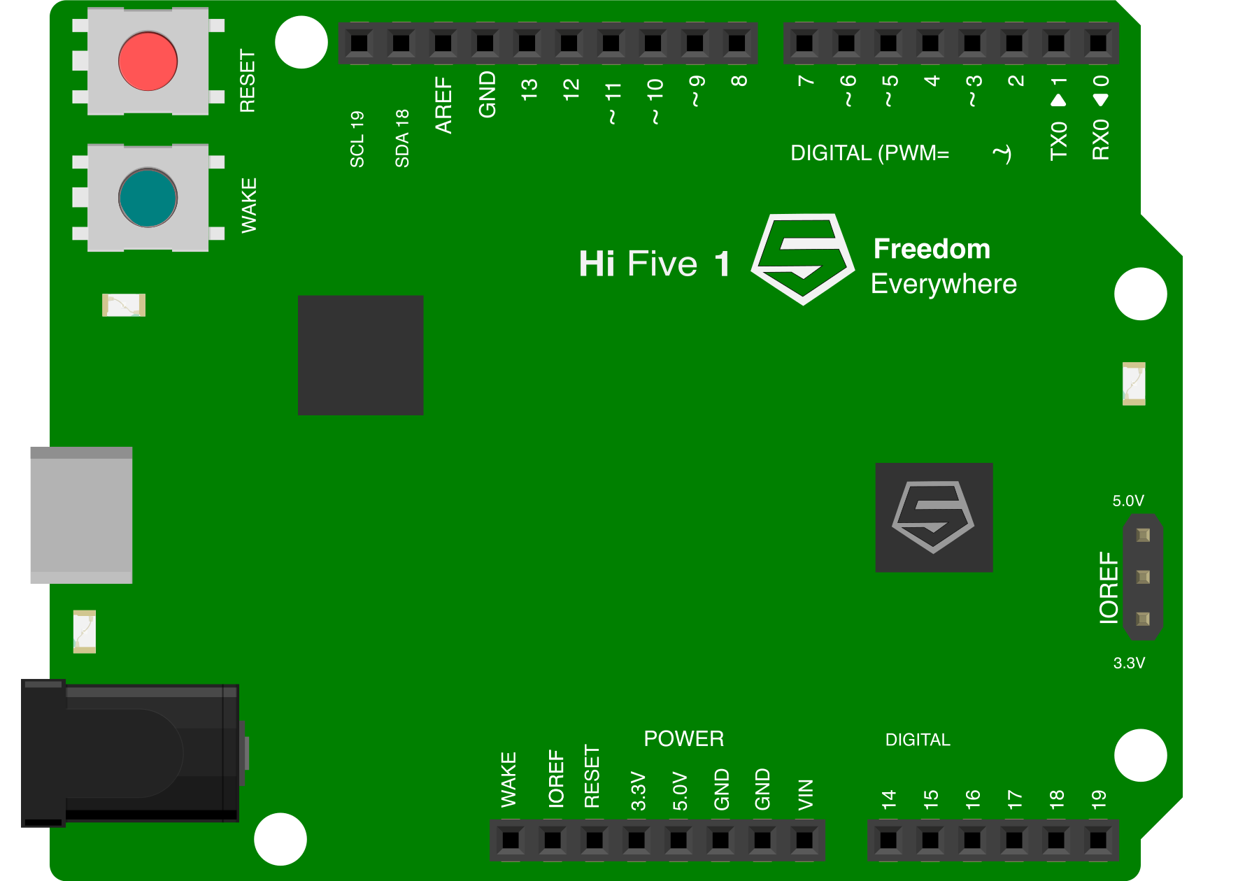
The HiFive1, manufactured by SiFive, is a RISC-V-based development board designed for prototyping and educational purposes. It features a 32-bit RISC-V processor, GPIO pins, and various interfaces for connecting sensors and peripherals. The HiFive1 is ideal for embedded systems projects, enabling developers to explore the capabilities of the open-source RISC-V architecture.
Explore Projects Built with HiFive1
 Open Project in Cirkit Designer
 Open Project in Cirkit Designer
 Open Project in Cirkit Designer
 Open Project in Cirkit Designer
Explore Projects Built with HiFive1
Open Project in Cirkit DesignerOpen Project in Cirkit DesignerOpen Project in Cirkit DesignerOpen Project in Cirkit DesignerCommon Applications and Use Cases
- Embedded systems development
- Educational projects for learning RISC-V architecture
- Prototyping IoT devices
- Sensor interfacing and data acquisition
- Robotics and automation projects
Technical Specifications
The HiFive1 development board is built around the SiFive FE310-G002 microcontroller, which is based on the RISC-V ISA. Below are the key technical details:
Key Technical Details
- Processor: SiFive FE310-G002 (32-bit RISC-V core)
- Clock Speed: Up to 320 MHz
- Flash Memory: 16 MB (external QSPI flash)
- SRAM: 16 KB
- GPIO Pins: 19 digital I/O pins
- Interfaces:
- SPI
- I2C
- UART
- Power Supply: 5V via USB or external power supply
- Operating Voltage: 3.3V (logic level)
- Debugging Interface: JTAG
- Dimensions: 68.6 mm x 53.3 mm
Pin Configuration and Descriptions
The HiFive1 board features a 40-pin header with the following pin assignments:
| Pin Number | Pin Name | Description |
|---|---|---|
| 1 | 3.3V | 3.3V power output |
| 2 | GND | Ground |
| 3 | IO0 | Digital I/O pin 0 |
| 4 | IO1 | Digital I/O pin 1 |
| 5 | IO2 | Digital I/O pin 2 |
| 6 | IO3 | Digital I/O pin 3 |
| 7 | IO4 | Digital I/O pin 4 |
| 8 | IO5 | Digital I/O pin 5 |
| 9 | IO6 | Digital I/O pin 6 |
| 10 | IO7 | Digital I/O pin 7 |
| 11 | IO8 | Digital I/O pin 8 |
| 12 | IO9 | Digital I/O pin 9 |
| 13 | IO10 | Digital I/O pin 10 |
| 14 | IO11 | Digital I/O pin 11 |
| 15 | IO12 | Digital I/O pin 12 |
| 16 | IO13 | Digital I/O pin 13 |
| 17 | SPI_CS | SPI Chip Select |
| 18 | SPI_MOSI | SPI Master Out Slave In |
| 19 | SPI_MISO | SPI Master In Slave Out |
| 20 | SPI_SCK | SPI Clock |
Usage Instructions
How to Use the HiFive1 in a Circuit
- Powering the Board: Connect the HiFive1 to your computer using a USB cable. The board can also be powered via an external 5V power supply.
- Programming the Board: Use the Arduino IDE or SiFive Freedom Studio to write and upload code to the HiFive1. Ensure the correct board and port are selected in the IDE.
- Connecting Peripherals: Use the GPIO pins to connect sensors, actuators, or other peripherals. Ensure that the voltage levels of the connected devices are compatible with the 3.3V logic level of the HiFive1.
- Debugging: Use the JTAG interface for advanced debugging and development.
Important Considerations and Best Practices
- Voltage Levels: Avoid connecting devices that operate at 5V logic levels directly to the GPIO pins, as this may damage the board.
- Pin Current Limits: Do not exceed the maximum current rating of the GPIO pins (typically 4-8 mA per pin).
- Static Protection: Handle the board with care to avoid damage from electrostatic discharge (ESD).
- Firmware Updates: Periodically check for firmware updates for the SiFive FE310-G002 to ensure optimal performance.
Example Code for Arduino IDE
Below is an example of how to blink an LED connected to GPIO pin 13:
// Blink an LED connected to GPIO pin 13 on the HiFive1 board

void setup() {
  pinMode(13, OUTPUT); // Set GPIO pin 13 as an output
}

void loop() {
  digitalWrite(13, HIGH); // Turn the LED on
  delay(1000);            // Wait for 1 second
  digitalWrite(13, LOW);  // Turn the LED off
  delay(1000);            // Wait for 1 second
}
Troubleshooting and FAQs
Common Issues and Solutions
The board is not detected by the computer:
- Ensure the USB cable is properly connected and supports data transfer.
- Check if the necessary drivers for the HiFive1 are installed on your computer.
- Try using a different USB port or cable.
Code upload fails:
- Verify that the correct board and port are selected in the Arduino IDE or Freedom Studio.
- Ensure no other application is using the serial port.
- Reset the board by pressing the reset button before uploading the code.
Peripherals are not working as expected:
- Double-check the wiring and connections.
- Ensure the voltage levels of the peripherals are compatible with the HiFive1.
- Test the peripherals independently to confirm they are functioning correctly.
LED does not blink in the example code:
- Ensure the LED is connected to GPIO pin 13 and the ground pin.
- Verify that the LED is not damaged and is oriented correctly (longer leg to GPIO pin 13).
FAQs
Can the HiFive1 run on battery power? Yes, the HiFive1 can be powered using an external 5V power supply, such as a battery pack.
Is the HiFive1 compatible with Arduino libraries? Many Arduino libraries are compatible with the HiFive1, but some may require modifications due to differences in architecture.
What is the maximum clock speed of the HiFive1? The HiFive1 can operate at a clock speed of up to 320 MHz.
Can I use the HiFive1 for commercial projects? Yes, the HiFive1 can be used for prototyping and commercial projects, but ensure compliance with any licensing requirements for the RISC-V architecture and associated software.
This concludes the documentation for the HiFive1 development board.