
How to Use POTENTIOMETER Mini: Examples, Pinouts, and Specs
 Design with POTENTIOMETER Mini in Cirkit Designer
Introduction
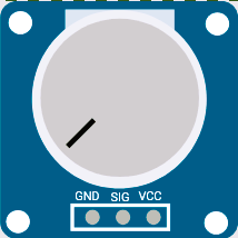
The POTENTIOMETER Mini is a small adjustable resistor designed to control voltage or current in electronic circuits. By varying its resistance, it allows users to fine-tune parameters such as signal strength, brightness, or motor speed. This component is widely used in applications like audio volume control, tuning circuits, and sensor calibration.
Explore Projects Built with POTENTIOMETER Mini
 Open Project in Cirkit Designer
 Open Project in Cirkit Designer
 Open Project in Cirkit Designer
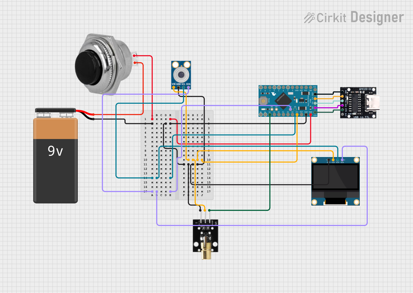 Open Project in Cirkit Designer
Explore Projects Built with POTENTIOMETER Mini
Open Project in Cirkit DesignerOpen Project in Cirkit DesignerOpen Project in Cirkit DesignerOpen Project in Cirkit DesignerCommon Applications:
- Audio volume control in amplifiers or speakers
- Brightness adjustment in LED circuits
- Motor speed control
- Calibration of sensors in microcontroller projects
- Tuning frequency in radio circuits
Technical Specifications
The following table outlines the key technical details of the POTENTIOMETER Mini:
| Parameter | Specification |
|---|---|
| Resistance Range | 1 kΩ to 1 MΩ (varies by model) |
| Power Rating | 0.1 W to 0.5 W |
| Tolerance | ±10% |
| Adjustment Type | Rotary |
| Operating Voltage | Up to 50 V |
| Operating Temperature | -10°C to +70°C |
| Lifespan | ~10,000 cycles |
Pin Configuration:
The POTENTIOMETER Mini typically has three pins, as described below:
| Pin | Name | Description |
|---|---|---|
| 1 | Terminal 1 | One end of the resistive track. Connect to one side of the circuit. |
| 2 | Wiper | The adjustable middle pin. Outputs the variable resistance or voltage. |
| 3 | Terminal 2 | The other end of the resistive track. Connect to the other side of the circuit. |
Usage Instructions
How to Use the POTENTIOMETER Mini in a Circuit:
- Identify the Pins: Locate the three pins (Terminal 1, Wiper, and Terminal 2). The wiper pin is usually the middle pin.
- Connect the Component:
- Connect Terminal 1 to the input voltage or signal source.
- Connect Terminal 2 to ground or the other side of the circuit.
- Connect the Wiper pin to the load or the part of the circuit where you need a variable voltage or resistance.
- Adjust the Resistance: Rotate the potentiometer's knob or shaft to change the resistance. This will vary the output voltage or current.
Important Considerations:
- Power Rating: Ensure the power dissipation does not exceed the potentiometer's rated power to avoid damage.
- Mechanical Stress: Avoid applying excessive force when turning the knob to prevent wear or breakage.
- Noise: In high-precision applications, note that potentiometers can introduce electrical noise when adjusted.
- Mounting: Secure the potentiometer properly to prevent movement during operation.
Example: Using the POTENTIOMETER Mini with an Arduino UNO
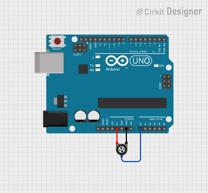
The following example demonstrates how to use the POTENTIOMETER Mini to read analog values and control the brightness of an LED.
Circuit Connections:
- Connect Terminal 1 to 5V on the Arduino.
- Connect Terminal 2 to GND on the Arduino.
- Connect the Wiper pin to the Arduino's analog input pin (e.g., A0).
- Connect an LED to pin 9 of the Arduino through a 220Ω resistor.
Code Example:
// POTENTIOMETER Mini Example: Adjust LED brightness using a potentiometer

const int potPin = A0;  // Analog pin connected to the potentiometer's wiper
const int ledPin = 9;   // PWM pin connected to the LED
int potValue = 0;       // Variable to store the potentiometer value
int ledBrightness = 0;  // Variable to store the LED brightness

void setup() {
  pinMode(ledPin, OUTPUT);  // Set the LED pin as an output
  Serial.begin(9600);       // Initialize serial communication for debugging
}

void loop() {
  potValue = analogRead(potPin);  // Read the potentiometer value (0-1023)

  // Map the potentiometer value to a PWM range (0-255)
  ledBrightness = map(potValue, 0, 1023, 0, 255);

  analogWrite(ledPin, ledBrightness);  // Set the LED brightness

  // Print the potentiometer value and LED brightness for debugging
  Serial.print("Potentiometer Value: ");
  Serial.print(potValue);
  Serial.print(" | LED Brightness: ");
  Serial.println(ledBrightness);

  delay(100);  // Small delay for stability
}
Troubleshooting and FAQs
Common Issues:
No Output Voltage:
- Cause: Incorrect wiring.
- Solution: Verify the connections to the potentiometer's pins. Ensure the wiper pin is connected to the load or input pin.
Inconsistent or Noisy Output:
- Cause: Dirty or worn resistive track.
- Solution: Clean the potentiometer with contact cleaner or replace it if worn out.
Overheating:
- Cause: Exceeding the power rating.
- Solution: Use a potentiometer with a higher power rating or reduce the current through the component.
Mechanical Failure:
- Cause: Excessive force applied to the knob.
- Solution: Replace the potentiometer and handle it gently during adjustments.
FAQs:
Q: Can I use the POTENTIOMETER Mini for digital signals?
A: No, potentiometers are designed for analog signals and cannot directly process digital signals.Q: How do I choose the correct resistance value for my application?
A: Select a resistance value that matches the voltage and current requirements of your circuit. For fine adjustments, use a higher resistance range.Q: Can I use the POTENTIOMETER Mini as a variable resistor (rheostat)?
A: Yes, by connecting only one terminal and the wiper pin, you can use it as a variable resistor.Q: What is the lifespan of the POTENTIOMETER Mini?
A: The typical lifespan is around 10,000 adjustment cycles, depending on usage and environmental conditions.