How to Use Fan 140mm: Examples, Pinouts, and Specs
Introduction
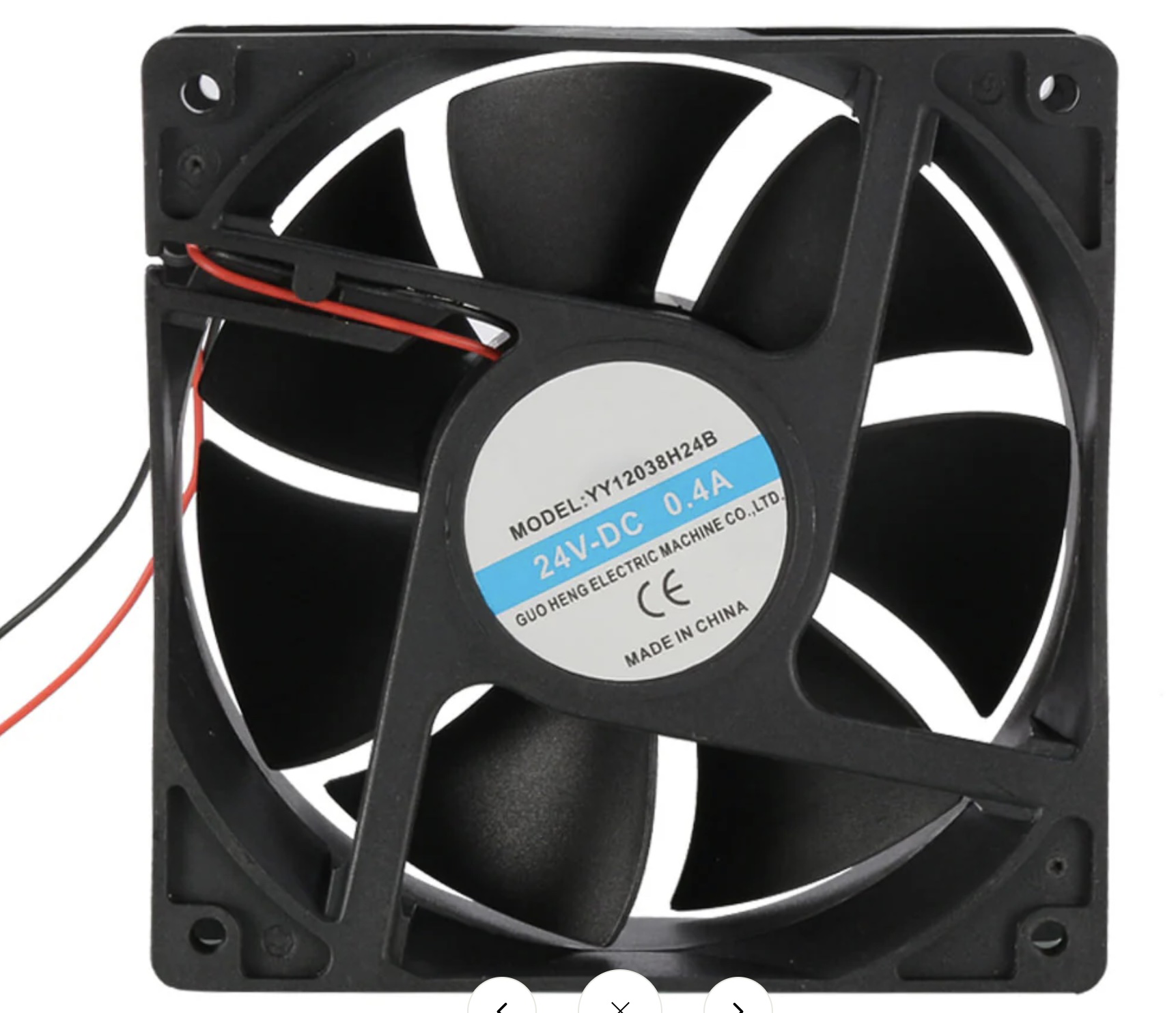
The 140mm cooling fan is an essential component widely used in computer systems to maintain optimal operating temperatures. Its primary function is to dissipate heat by circulating air across heat-generating components such as CPUs, GPUs, and power supplies. The 140mm size refers to the fan's diameter, making it suitable for cases and heat sinks that accommodate this size.
Explore Projects Built with Fan 140mm

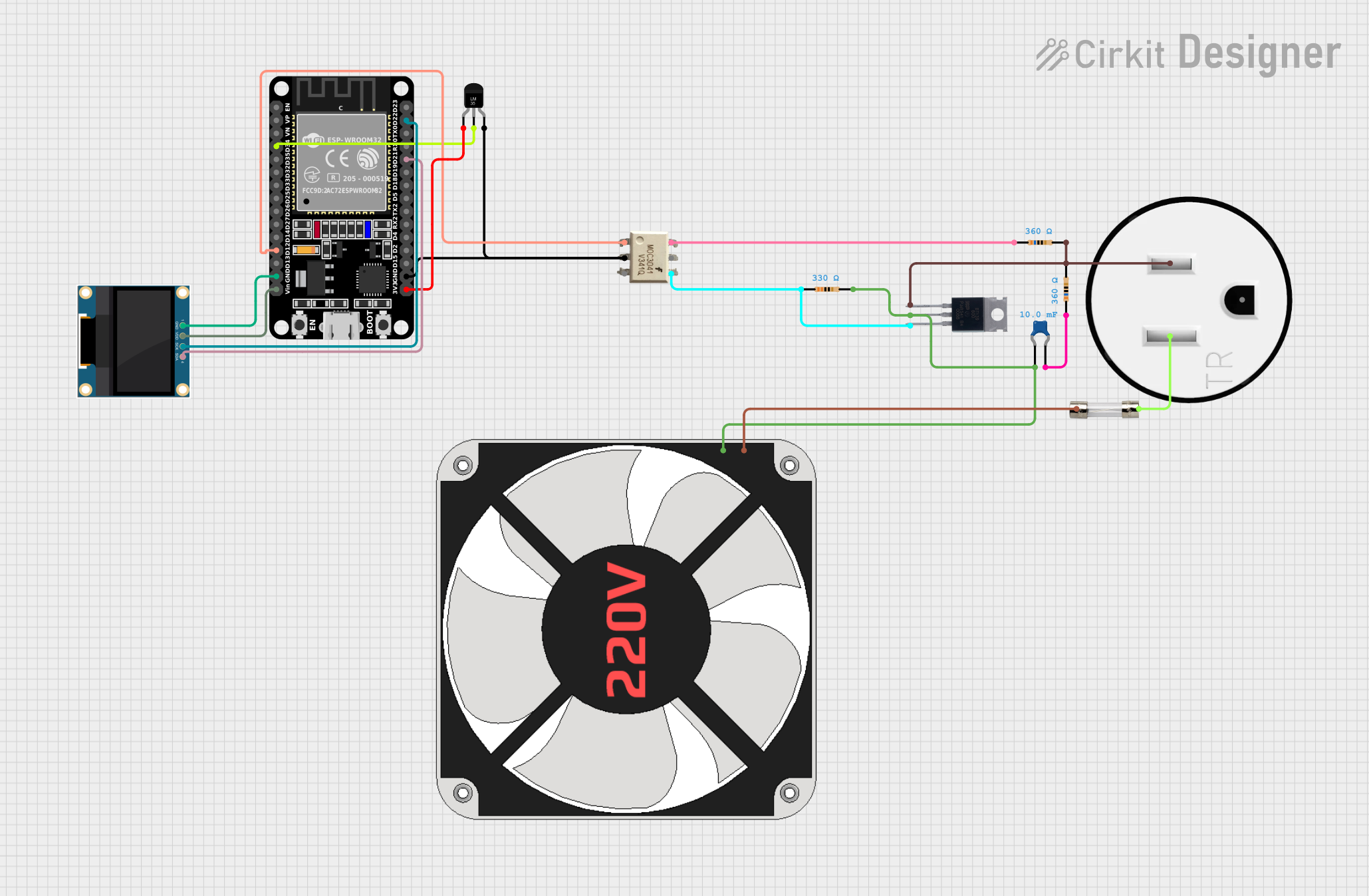

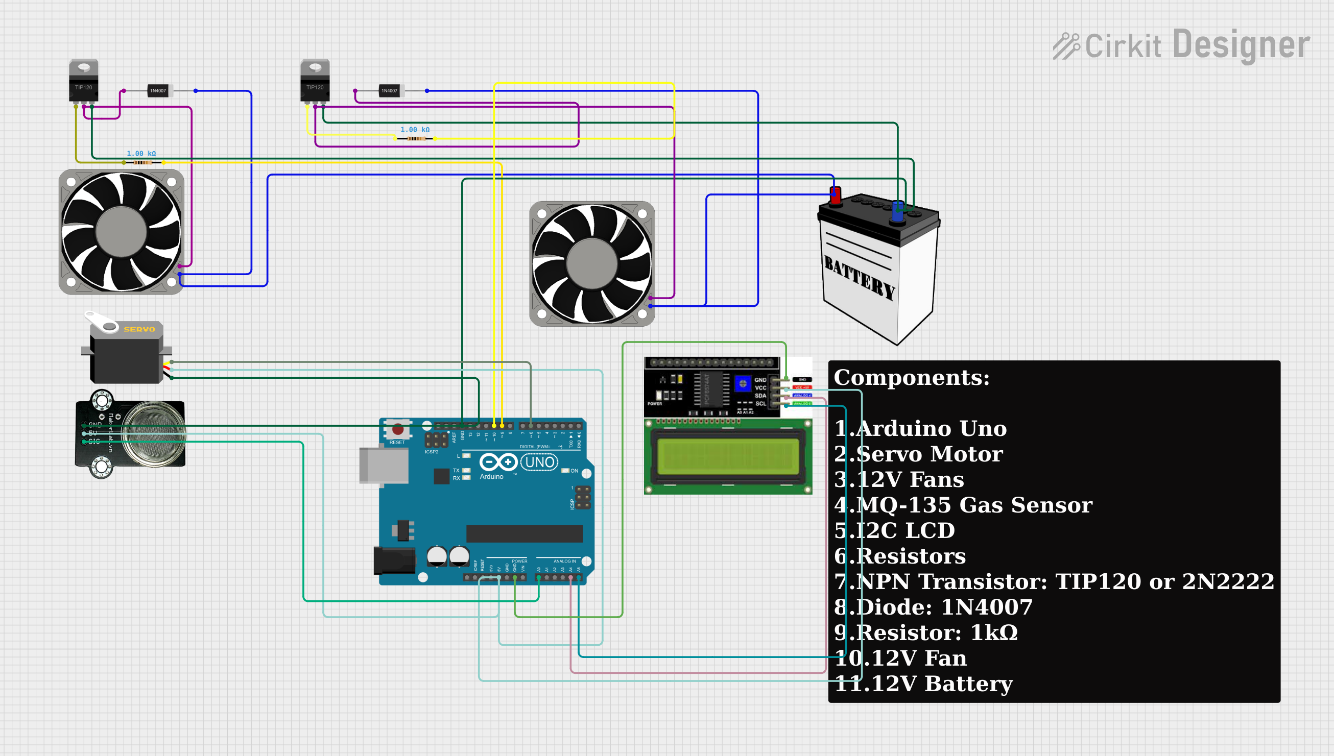
Explore Projects Built with Fan 140mm
Common Applications and Use Cases
- Computer cases for airflow management
- CPU and GPU coolers for enhanced heat dissipation
- Power supply units to prevent overheating
- Server racks and data centers for thermal regulation
- Electronic enclosures where heat buildup is a concern
Technical Specifications
Key Technical Details
| Specification | Value/Description |
|---|---|
| Voltage | 12V DC |
| Current | 0.30A |
| Power Consumption | 3.6W |
| Speed | 1000 RPM |
| Airflow | 64 CFM |
| Noise Level | 25 dBA |
| Bearing Type | Sleeve/Ball |
| Connector Type | 3-pin/4-pin PWM |
Pin Configuration and Descriptions
| Pin Number | Description | Wire Color (Typical) |
|---|---|---|
| 1 | Ground | Black |
| 2 | +12V Power Supply | Red/Yellow |
| 3 | Tachometer Signal | Green/Blue |
| 4 | PWM Control Signal* | Blue/White |
* Note: The 4th pin is present only on 4-pin PWM fans.
Usage Instructions
How to Use the Component in a Circuit
- Power Connection: Connect the fan's power supply pin to a 12V DC source and the ground pin to the common ground in your circuit.
- PWM Control (Optional): For fans with a 4-pin connector, the PWM control signal can be used to adjust the fan speed. Connect this to a PWM-capable pin on your controller.
- Tachometer Reading: The tachometer signal provides feedback on the fan's speed. Connect this to a digital input on your controller if fan speed monitoring is required.
Important Considerations and Best Practices
- Ensure the fan is mounted securely to prevent vibrations and noise.
- Verify the airflow direction (usually indicated by an arrow on the fan housing) to ensure proper cooling.
- Do not obstruct the fan's intake or exhaust areas.
- Regularly clean the fan blades and housing to maintain optimal performance.
- Use appropriate pulse-width modulation (PWM) techniques for speed control to avoid damaging the fan.
Troubleshooting and FAQs
Common Issues
- Fan Not Starting: Check the power supply voltage and connections.
- Noisy Operation: Ensure the fan is securely mounted and free of dust.
- Inconsistent Speed: Verify that the PWM signal (if used) is correct and stable.
Solutions and Tips for Troubleshooting
- If the fan does not start, verify that the power supply is providing 12V and that the connections are secure.
- For noise issues, check for loose parts and clean any dust buildup.
- Inconsistent speed or failure to respond to PWM signals may indicate a problem with the controller or the PWM signal itself.
FAQs
Q: Can I run the fan at a lower voltage for quieter operation? A: Yes, but be aware that running the fan at a voltage significantly lower than 12V may result in reduced performance or failure to start.
Q: How do I know if my fan supports PWM? A: Check for a 4-pin connector; fans with PWM control typically use this type of connector.
Q: What is the lifespan of a 140mm cooling fan? A: Lifespan varies based on bearing type and usage conditions but typically ranges from 30,000 to 70,000 hours.
Example Arduino Code for PWM Control
// Define the PWM pin connected to the fan
const int pwmPin = 9; // For Arduino UNO, use pins 3, 5, 6, 9, 10, or 11 for PWM

void setup() {
  // Set the PWM pin as an output
  pinMode(pwmPin, OUTPUT);
}

void loop() {
  // Set the fan speed to 50% duty cycle
  analogWrite(pwmPin, 127); // 127 out of 255 for 50%
  delay(5000); // Run at this speed for 5 seconds

  // Increase the fan speed to 75% duty cycle
  analogWrite(pwmPin, 191); // 191 out of 255 for 75%
  delay(5000); // Run at this speed for 5 seconds

  // Turn off the fan
  analogWrite(pwmPin, 0); // 0 out of 255 for 0%
  delay(5000); // Fan is off for 5 seconds

  // Note: Ensure your fan is rated for PWM control before using this code.
}
Note: The provided code is a basic example of how to control a 4-pin PWM fan using an Arduino UNO. Adjust the analogWrite values to change the fan speed as needed. Ensure that the fan's PWM control pin is connected to one of the Arduino's PWM-capable pins.