How to Use Charging Module: Examples, Pinouts, and Specs
Introduction
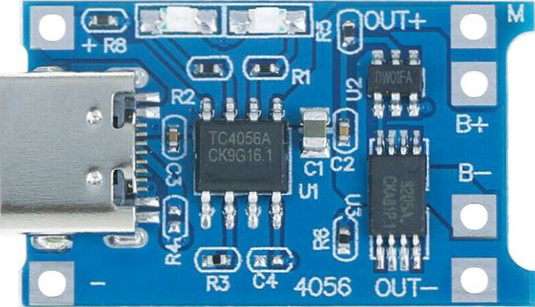
The Charging Module (Type-C) by Generic is a compact and efficient device designed to manage the charging of batteries. It ensures safe and reliable charging by regulating the voltage and current supplied to the battery. This module is commonly used in portable electronics, DIY projects, and battery-powered devices to prevent overcharging and extend battery life.
Explore Projects Built with Charging Module


Explore Projects Built with Charging Module
Common Applications and Use Cases
- Charging lithium-ion (Li-ion) and lithium-polymer (LiPo) batteries
- Power management in portable devices
- DIY electronics projects
- Battery-powered IoT devices
- Robotics and small-scale energy storage systems
Technical Specifications
The following table outlines the key technical details of the Charging Module (Type-C):
| Parameter | Value |
|---|---|
| Input Voltage | 5V (via USB Type-C connector) |
| Charging Voltage | 4.2V ± 1% |
| Maximum Charging Current | 1A |
| Battery Type Supported | Single-cell Li-ion/LiPo batteries |
| Dimensions | 25mm x 19mm x 2.5mm |
| Operating Temperature | -10°C to 85°C |
Pin Configuration and Descriptions
The Charging Module features the following pins and connectors:
| Pin/Connector | Description |
|---|---|
| Type-C Input | USB Type-C connector for 5V power input. |
| BAT+ | Positive terminal for connecting the battery. |
| BAT- | Negative terminal for connecting the battery. |
| OUT+ | Positive terminal for output voltage (connected to the load). |
| OUT- | Negative terminal for output voltage (connected to the load). |
| CHG LED | LED indicator for charging status (ON when charging, OFF when fully charged). |
| PWR LED | LED indicator for power input status (ON when power is supplied). |
Usage Instructions
How to Use the Charging Module in a Circuit
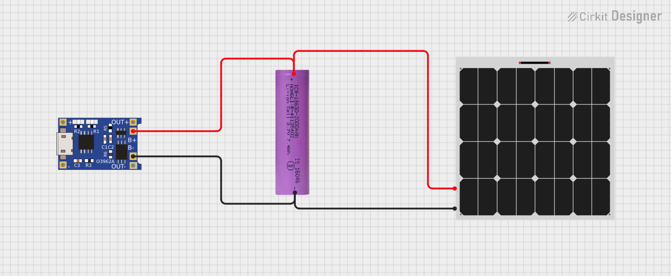
- Connect the Battery:
- Connect the positive terminal of the battery to the
BAT+pin. - Connect the negative terminal of the battery to the
BAT-pin.
- Connect the positive terminal of the battery to the
- Connect the Load (Optional):
- If you want to power a load while charging the battery, connect the load's positive terminal to
OUT+and the negative terminal toOUT-.
- If you want to power a load while charging the battery, connect the load's positive terminal to
- Power the Module:
- Supply 5V input power to the module via the USB Type-C connector.
- Monitor the LEDs:
- The
CHG LEDwill light up during charging and turn off when the battery is fully charged. - The
PWR LEDwill light up when the module is powered.
- The
Important Considerations and Best Practices
- Ensure the battery being charged is a single-cell Li-ion or LiPo battery with a nominal voltage of 3.7V.
- Do not exceed the maximum input voltage of 5V to avoid damaging the module.
- Avoid short-circuiting the
BAT+andBAT-terminals. - Use appropriate heat dissipation methods if the module operates at high currents for extended periods.
- For safety, always monitor the charging process and avoid leaving the module unattended.
Example: Using the Charging Module with an Arduino UNO
The Charging Module can be used to power an Arduino UNO via its OUT+ and OUT- terminals. Below is an example code snippet to monitor the battery voltage using the Arduino UNO:
// Example code to monitor battery voltage using Arduino UNO
const int batteryPin = A0; // Analog pin connected to BAT+ terminal
float batteryVoltage = 0.0;

void setup() {
  Serial.begin(9600); // Initialize serial communication
  pinMode(batteryPin, INPUT); // Set the battery pin as input
}

void loop() {
  int sensorValue = analogRead(batteryPin); // Read the analog value
  // Convert the analog value to voltage (assuming a 5V reference and 10-bit ADC)
  batteryVoltage = sensorValue * (5.0 / 1023.0) * 2;
  // Multiply by 2 due to voltage divider (if used)

  Serial.print("Battery Voltage: ");
  Serial.print(batteryVoltage);
  Serial.println(" V");

  delay(1000); // Wait for 1 second before the next reading
}
Note: If the battery voltage exceeds 5V, use a voltage divider to scale it down before connecting to the Arduino's analog pin.
Troubleshooting and FAQs
Common Issues and Solutions
The module does not power on:
- Ensure the USB Type-C cable is properly connected and supplying 5V.
- Check the
PWR LEDto confirm power input status.
Battery is not charging:
- Verify the battery connections to
BAT+andBAT-. - Ensure the battery is a single-cell Li-ion or LiPo type.
- Check if the
CHG LEDis lit. If not, inspect the input voltage and current.
- Verify the battery connections to
Overheating during operation:
- Reduce the charging current if possible.
- Ensure proper ventilation around the module.
Load not receiving power:
- Confirm the load is connected to
OUT+andOUT-. - Check the battery voltage to ensure it is sufficient to power the load.
- Confirm the load is connected to
Frequently Asked Questions
Q1: Can I use this module to charge multiple batteries in series?
A1: No, this module is designed for single-cell Li-ion or LiPo batteries only. Charging multiple batteries in series requires a specialized charger.
Q2: What happens if I leave the battery connected after it is fully charged?
A2: The module includes overcharge protection and will stop charging the battery once it is fully charged. However, it is recommended to disconnect the battery to prevent unnecessary power consumption.
Q3: Can I use a power bank as the input source?
A3: Yes, a power bank can be used as long as it provides a stable 5V output.
Q4: Is it safe to use this module for long-term charging?
A4: While the module has built-in safety features, it is best to monitor the charging process and avoid prolonged unattended use.
By following this documentation, you can safely and effectively use the Charging Module (Type-C) in your projects.