Cirkit Designer Logo
Cirkit Designer
Your all-in-one circuit design IDE
Home / 
Component Documentation

How to Use PowerBoost 500 Charger USB: Examples, Pinouts, and Specs

Image of PowerBoost 500 Charger USB
Cirkit Designer LogoDesign with PowerBoost 500 Charger USB in Cirkit Designer

Introduction

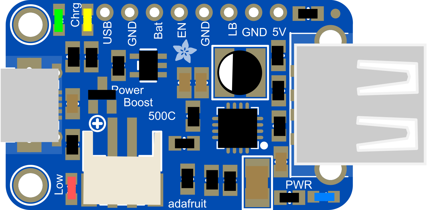
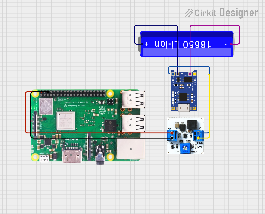
The PowerBoost 500 Charger USB is a versatile and compact electronic module designed to provide a 5V power supply with a current up to 500mA. It combines a boost converter with a USB charging circuit, making it ideal for portable electronics, DIY projects, and any application requiring a stable 5V supply from a lower voltage source, such as a single-cell lithium-polymer (LiPo) battery. Common applications include USB-powered gadgets, wearable electronics, and as a power backup for single-board computers like the Raspberry Pi.

Explore Projects Built with PowerBoost 500 Charger USB

Use Cirkit Designer to design, explore, and prototype these projects online. Some projects support real-time simulation. Click "Open Project" to start designing instantly!
Battery-Powered Raspberry Pi 3B+ with TP4056 and DC/DC Booster
Image of raspberry power supply: A project utilizing PowerBoost 500 Charger USB in a practical application
This circuit is a portable power supply system that charges a 18650 Li-ion battery using a TP4056 charging module and boosts the voltage to power a Raspberry Pi 3b+ via a DC/DC booster. The TP4056 module manages the charging of the battery, while the DC/DC booster converts the battery voltage to a stable 5V output for the Raspberry Pi.
Cirkit Designer LogoOpen Project in Cirkit Designer
Battery-Powered USB Charger with LED Indicator and DC Motor
Image of Copy of Hand Crank mobile charger : A project utilizing PowerBoost 500 Charger USB in a practical application
This circuit converts AC power to DC using a bridge rectifier and regulates the voltage to 5V with a 7805 voltage regulator. It powers a USB port and indicates power status with an LED, while also providing a charging interface through a multi-charging cable.
Cirkit Designer LogoOpen Project in Cirkit Designer
Battery-Powered DC Motor Control with USB Charging and LED Indicator
Image of lumantas: A project utilizing PowerBoost 500 Charger USB in a practical application
This circuit is designed to charge a Li-ion battery and power a DC motor and a 12V LED. The TP4056 module manages the battery charging process, while the PowerBoost 1000 and MT3608 boost converters step up the voltage to drive the motor and LED, respectively. Two rocker switches control the power flow to the LED and the charging circuit.
Cirkit Designer LogoOpen Project in Cirkit Designer
Battery-Powered 18650 Li-ion Charger with USB Output and Adjustable Voltage Regulator
Image of Breadboard: A project utilizing PowerBoost 500 Charger USB in a practical application
This circuit is a battery management and power supply system that uses three 3.7V batteries connected to a 3S 10A Li-ion 18650 Charger Protection Board Module for balanced charging and protection. The system includes a TP4056 Battery Charging Protection Module for additional charging safety, a Step Up Boost Power Converter to regulate and boost the voltage, and a USB regulator to provide a stable 5V output, controlled by a push switch.
Cirkit Designer LogoOpen Project in Cirkit Designer

Explore Projects Built with PowerBoost 500 Charger USB

Use Cirkit Designer to design, explore, and prototype these projects online. Some projects support real-time simulation. Click "Open Project" to start designing instantly!
Image of raspberry power supply: A project utilizing PowerBoost 500 Charger USB in a practical application
Battery-Powered Raspberry Pi 3B+ with TP4056 and DC/DC Booster
This circuit is a portable power supply system that charges a 18650 Li-ion battery using a TP4056 charging module and boosts the voltage to power a Raspberry Pi 3b+ via a DC/DC booster. The TP4056 module manages the charging of the battery, while the DC/DC booster converts the battery voltage to a stable 5V output for the Raspberry Pi.
Cirkit Designer LogoOpen Project in Cirkit Designer
Image of Copy of Hand Crank mobile charger : A project utilizing PowerBoost 500 Charger USB in a practical application
Battery-Powered USB Charger with LED Indicator and DC Motor
This circuit converts AC power to DC using a bridge rectifier and regulates the voltage to 5V with a 7805 voltage regulator. It powers a USB port and indicates power status with an LED, while also providing a charging interface through a multi-charging cable.
Cirkit Designer LogoOpen Project in Cirkit Designer
Image of lumantas: A project utilizing PowerBoost 500 Charger USB in a practical application
Battery-Powered DC Motor Control with USB Charging and LED Indicator
This circuit is designed to charge a Li-ion battery and power a DC motor and a 12V LED. The TP4056 module manages the battery charging process, while the PowerBoost 1000 and MT3608 boost converters step up the voltage to drive the motor and LED, respectively. Two rocker switches control the power flow to the LED and the charging circuit.
Cirkit Designer LogoOpen Project in Cirkit Designer
Image of Breadboard: A project utilizing PowerBoost 500 Charger USB in a practical application
Battery-Powered 18650 Li-ion Charger with USB Output and Adjustable Voltage Regulator
This circuit is a battery management and power supply system that uses three 3.7V batteries connected to a 3S 10A Li-ion 18650 Charger Protection Board Module for balanced charging and protection. The system includes a TP4056 Battery Charging Protection Module for additional charging safety, a Step Up Boost Power Converter to regulate and boost the voltage, and a USB regulator to provide a stable 5V output, controlled by a push switch.
Cirkit Designer LogoOpen Project in Cirkit Designer

Technical Specifications

Key Technical Details

  • Input Voltage: 1.8V to 5.5V
  • Output Voltage: 5V regulated
  • Output Current: Up to 500mA
  • Efficiency: 90% typical at full load
  • USB Charging Port: Standard Type-A
  • Battery Charging Support: For 3.7V LiPo batteries
  • Integrated Protection: Over-temperature, over-current, and short-circuit protection

Pin Configuration and Descriptions

Pin Name Description
VBAT Battery input voltage (1.8V to 5.5V)
GND Ground connection
5V Regulated 5V output
EN Enable pin (active high)
USB USB output (Type-A port)
BAT Connection for LiPo battery
GND Ground for battery

Usage Instructions

Integrating into a Circuit

  1. Power Connection: Connect the VBAT pin to your battery or unregulated power source, and the GND pin to the common ground.
  2. Enabling the Module: The EN pin can be left unconnected for normal operation, or connected to a logic high signal to enable the boost converter.
  3. Output: Use the 5V pin to power your 5V electronics, or use the USB port to charge USB devices.
  4. Battery Charging: Connect a 3.7V LiPo battery to the BAT and GND pins for integrated charging capability.

Best Practices

  • Ensure the input voltage does not exceed 5.5V to prevent damage.
  • Avoid drawing more than 500mA from the output to maintain efficiency and prevent overheating.
  • Use proper heat dissipation techniques if operating near full load for extended periods.
  • When charging a battery, make sure to use a battery with a protection circuit.

Troubleshooting and FAQs

Common Issues

  • Insufficient Output Current: Ensure the input power source can supply enough current and is within the specified voltage range.
  • Module Overheating: Reduce the load if the module is too hot to touch or consider adding a heatsink.
  • Device Not Charging: Check the USB cable and connections, and ensure the battery is properly connected and not depleted beyond charging threshold.

FAQs

Q: Can I use the PowerBoost 500 Charger to charge my phone? A: Yes, as long as your phone charges via USB and requires 500mA or less.

Q: What should I do if the PowerBoost 500 Charger is not turning on? A: Verify all connections, ensure the input voltage is within range, and check that the EN pin is either unconnected or driven high.

Q: Can the PowerBoost 500 Charger be used while charging a battery? A: Yes, it supports load sharing, allowing the device to operate while the battery is charging.

Example Code for Arduino UNO

// Example code to enable the PowerBoost 500 Charger via an Arduino UNO

const int enablePin = 7; // Connect the EN pin of PowerBoost to digital pin 7

void setup() {
  pinMode(enablePin, OUTPUT); // Set the enable pin as an output
  digitalWrite(enablePin, HIGH); // Turn on the PowerBoost 500 Charger
}

void loop() {
  // Your code to interact with the powered device goes here
}

Note: This code snippet demonstrates how to enable the PowerBoost 500 Charger using an Arduino UNO. The EN pin is connected to digital pin 7, which is set to HIGH to activate the boost converter.