How to Use ESP32: Examples, Pinouts, and Specs
Introduction
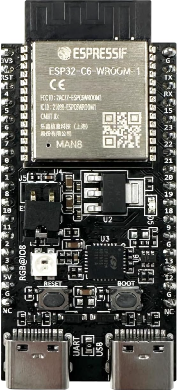
The ESP32, manufactured by Espressif, is a low-cost, low-power system on a chip (SoC) with integrated Wi-Fi and Bluetooth capabilities. It is designed for a wide range of applications, including Internet of Things (IoT) devices, smart home systems, wearable electronics, and embedded systems. The ESP32-C6-DevKitC-1-N8 is a development board that simplifies prototyping and development with the ESP32 SoC.
With its dual-core processor, extensive GPIO options, and support for multiple communication protocols, the ESP32 is a versatile and powerful solution for developers looking to create connected devices.
Explore Projects Built with ESP32


Explore Projects Built with ESP32
Common Applications
- IoT devices (e.g., smart sensors, connected appliances)
- Home automation systems
- Wearable electronics
- Wireless communication bridges
- Industrial automation and monitoring
- Prototyping and educational projects
Technical Specifications
Key Technical Details
| Parameter | Specification |
|---|---|
| Manufacturer | Espressif |
| Part ID | ESP32-C6-DevKitC-1-N8 |
| Processor | Dual-core Xtensa® 32-bit LX6 microprocessor |
| Clock Speed | Up to 240 MHz |
| Flash Memory | 8 MB (N8 variant) |
| RAM | 512 KB SRAM |
| Wireless Connectivity | Wi-Fi 802.11 b/g/n, Bluetooth 4.2 and BLE |
| Operating Voltage | 3.3V |
| GPIO Pins | 34 (multipurpose, including ADC, DAC, PWM, etc.) |
| Communication Interfaces | UART, SPI, I2C, I2S, CAN, Ethernet, SDIO |
| Power Consumption | Ultra-low power in deep sleep mode (~10 µA) |
| Operating Temperature | -40°C to +85°C |
Pin Configuration and Descriptions
The ESP32-C6-DevKitC-1-N8 development board features a 38-pin layout. Below is a summary of the key pins and their functions:
| Pin Number | Pin Name | Functionality |
|---|---|---|
| 1 | GND | Ground |
| 2 | 3V3 | 3.3V power supply |
| 3 | EN | Enable pin (active high) |
| 4 | IO0 | GPIO0, used for boot mode selection |
| 5 | IO2 | GPIO2, ADC, DAC, or PWM |
| 6 | IO4 | GPIO4, ADC, or PWM |
| 7 | IO5 | GPIO5, ADC, or PWM |
| 8 | IO12 | GPIO12, ADC, or PWM |
| 9 | IO13 | GPIO13, ADC, or PWM |
| 10 | IO14 | GPIO14, ADC, or PWM |
| 11 | IO15 | GPIO15, ADC, or PWM |
| 12 | IO16 | GPIO16, UART RX |
| 13 | IO17 | GPIO17, UART TX |
| 14 | IO18 | GPIO18, SPI CLK |
| 15 | IO19 | GPIO19, SPI MISO |
| 16 | IO21 | GPIO21, I2C SDA |
| 17 | IO22 | GPIO22, I2C SCL |
| 18 | IO23 | GPIO23, SPI MOSI |
| 19 | IO25 | GPIO25, DAC1 |
| 20 | IO26 | GPIO26, DAC2 |
| 21 | IO27 | GPIO27, ADC or PWM |
| 22 | IO32 | GPIO32, ADC or PWM |
| 23 | IO33 | GPIO33, ADC or PWM |
| 24 | IO34 | GPIO34, ADC (input only) |
| 25 | IO35 | GPIO35, ADC (input only) |
Usage Instructions
How to Use the ESP32 in a Circuit
- Power Supply: Provide a stable 3.3V power supply to the
3V3pin. Ensure the ground (GND) is connected to the circuit's ground. - Programming: Use a USB-to-serial adapter or the onboard USB port to upload code to the ESP32. The board is compatible with the Arduino IDE, ESP-IDF, and other development environments.
- Boot Mode: To enter bootloader mode for programming, hold the
BOOTbutton while pressing theEN(reset) button. - GPIO Usage: Configure GPIO pins as input, output, or for specific functions (e.g., ADC, PWM) in your code. Avoid using GPIO6-GPIO11 as they are connected to the onboard flash memory.
Important Considerations
- Voltage Levels: The ESP32 operates at 3.3V logic levels. Avoid connecting 5V signals directly to GPIO pins.
- Power Consumption: Use deep sleep mode to minimize power consumption in battery-powered applications.
- Antenna Placement: Ensure the onboard antenna has sufficient clearance from metal objects to avoid interference.
Example Code for Arduino UNO Integration
Below is an example of using the ESP32 with the Arduino IDE to blink an LED connected to GPIO2:
// Define the GPIO pin for the LED
#define LED_PIN 2

void setup() {
  // Initialize the LED pin as an output
  pinMode(LED_PIN, OUTPUT);
}

void loop() {
  // Turn the LED on
  digitalWrite(LED_PIN, HIGH);
  delay(1000); // Wait for 1 second

  // Turn the LED off
  digitalWrite(LED_PIN, LOW);
  delay(1000); // Wait for 1 second
}
Troubleshooting and FAQs
Common Issues
ESP32 Not Detected by Computer:
- Ensure the correct USB driver is installed for the USB-to-serial chip on the development board.
- Check the USB cable for data transfer capability (some cables are power-only).
Code Upload Fails:
- Verify the correct COM port is selected in the Arduino IDE or ESP-IDF.
- Hold the
BOOTbutton while pressing theENbutton to enter bootloader mode.
Wi-Fi Connection Issues:
- Double-check the SSID and password in your code.
- Ensure the Wi-Fi network is within range and not using unsupported security protocols.
GPIO Pin Not Working:
- Confirm the pin is not reserved for internal functions (e.g., GPIO6-GPIO11).
- Check for short circuits or incorrect wiring.
Tips for Troubleshooting
- Use the serial monitor to debug your code and view error messages.
- Test the ESP32 with a simple sketch (e.g., blinking an LED) to verify basic functionality.
- Refer to the Espressif documentation for advanced debugging techniques and tools.